Optical filter

Inactive Publication Date: 2006-09-07
HON HAI PRECISION IND CO LTD
View PDF14 Cites 20 Cited by
  • Summary
  • Abstract
  • Description
  • Claims
  • Application Information

AI Technical Summary

Benefits of technology

[0009] Each of the lower filter cavities consists of two high refractive index layers and one low refractive index layer sandwiched between the high refractive index layers. Each high refractive index layer of the lower filter cavities has a thickness equal to 0.5 times one eighth of a central wavelength associated therewith. Each low refractive index layer of the lower filter cavities has a thickness equal to 0.5 times one fourth of a central wavelength associated therewith.
[0010] Each of the upper filter cavities consists of two low refractive index layers and one high refractive index layer sandwiched between the low refractive index layers. The upper filter cavities includes a first filter cavity having a high refractive index layer thereof having a thickness equal to 1.666 times one fourth of a central wavelength associated therewith, and low refractive index layers thereof each having a thickness equal to 1.666 times one eighth of a central wavelength associated therewith; second filter cavities each having a high refractive index layer thereof having a thickness equal to 1.

Problems solved by technology

They are composed of many thin layers of dielectric materials, which have differing refractive indices to produce constructive and destructive interference in the transmitted light.
The range limitations are usually dependant upon the interference filters lens, and the

Method used


Image

  • Optical filter
  • Optical filter
  • Optical filter

Examples


Embodiment Construction

[0020] Reference will now be made to the drawings to describe embodiments of the present invention, in detail.

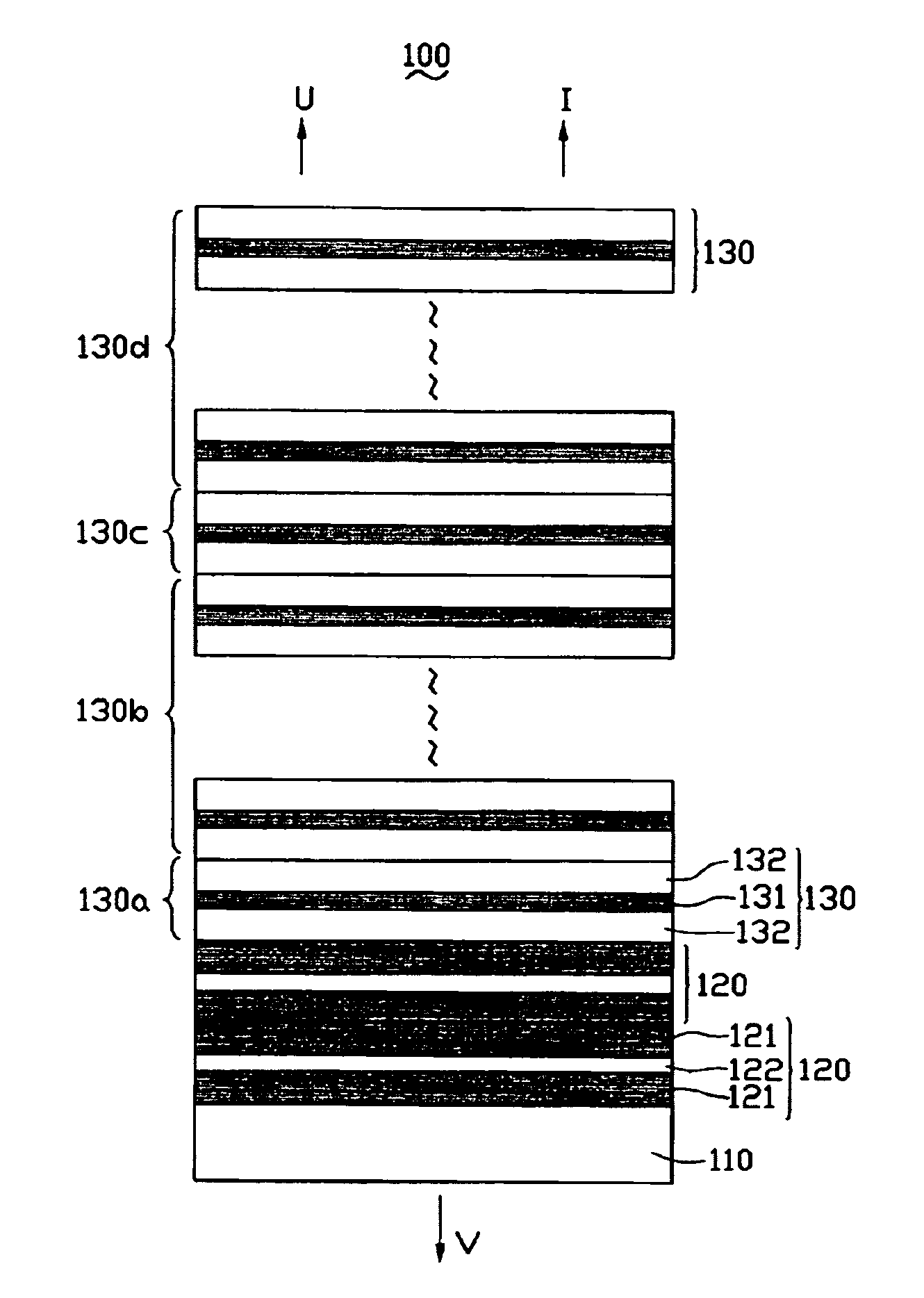
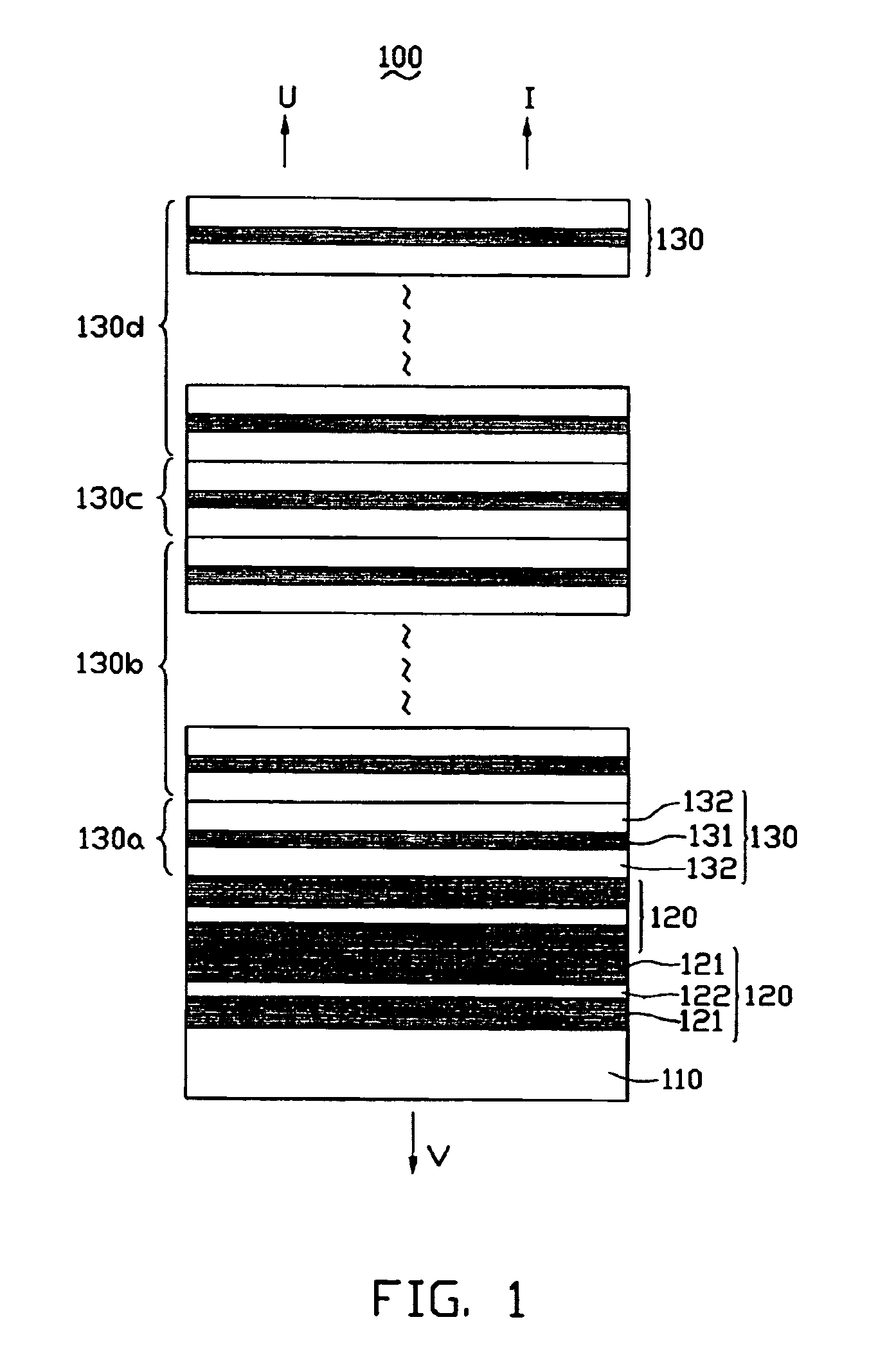
[0021] Referring to FIG. 1, an optical filter 100 according to a preferred embodiment is shown. The optical filter 100 includes a substrate 110, two contiguous identical lower filter cavities 120 formed on the substrate 110 and a number of contiguous upper filter cavities 130 formed on the lower filter cavities 120. Each of the lower filter cavities 120 consists of two high refractive index layers 121 and one low refractive index layer 122 sandwiched between the high refractive index layers 121. Each high refractive index layer 121 of the lower filter cavities has a thickness equal to 0.5 times one eighth of a central wavelength associated with the optical filter 100. Each low refractive index layer 122 of the lower filter cavities has a thickness equal to 0.5 times one fourth of a central wavelength associated therewith.

[0022] Each of the upper filter cavities 130 consist...


PUM


Abstract

An optical filter (100) includes a substrate (110), a number of contiguous identical lower filter cavities (120) formed on the substrate and a number of contiguous upper filter cavities (130) formed on the lower filter cavities. Each of the lower filter cavities consists of two high refractive index layers (121) and one low refractive index layer (122) sandwiched between the high refractive index layers. Each of the upper filter cavities consists of two low refractive index layers (132) and one high refractive index layer (131) sandwiched between the low refractive index layers. The present invention calculates optimal thicknesses for each layer, so that can shield infrared and ultra violet radiation precisely.

Description

FIELD OF THE INVENTION [0001] The invention relates generally to an optical filter, more particularly, to an optical filter which is capable of shielding / blocking light in infrared (IR) and ultra violet (UV) wavebands and has high transmittance at the visible light waveband. DESCRIPTION OF RELATED ART [0002] Optical filters are designed to transmit a specific waveband or reduce a spectral range (bandpass, cut off, and interference filter). They are composed of many thin layers of dielectric materials, which have differing refractive indices to produce constructive and destructive interference in the transmitted light. In this way, optical filters can be used to transmit a specific waveband and cut off undesired wavelength range. For example, optical filters capable of shielding UV and IR wavebands are used as car's windows for reducing temperature inside the car. The range limitations are usually dependant upon the interference filters lens, and the composition of the thin film filt...

Claims


Application Information

Patent Timeline
IPC IPC(8): G02B1/10
CPCG02B5/288
Inventor CHEN, GA-LANE
Owner HON HAI PRECISION IND CO LTD
Why Eureka
Try Eureka