Magnetic stimulator

a magnetic stimulation and tissue technology, applied in magnetotherapy, magnetotherapy using coils/electromagnets, magnetotherapy, etc., can solve the problems of skin or muscle twitching or pain, invasive electrical stimulation of tissue below the skin of a subject, and reducing the efficiency of intercellular links

Inactive Publication Date: 2006-09-07
EISENBERG SOLOMONR +1
View PDF3 Cites 107 Cited by
  • Summary
  • Abstract
  • Description
  • Claims
  • Application Information

AI Technical Summary

Benefits of technology

[0012] Embodiments of the present invention enable a target region of interest to be magnetically stimulated, without necessarily stimulating adjacent regions or regions that lie between the surface and the target region. Some embodiments of the invention utilize at least two time-varying magnetic fields that create intersecting electric fields in the target region. The region where the electric fields intersect is called an “intersection region.” The magnetic fields, and therefore the electric fields, operate at different frequencies and thus produce a beat frequency electric signal in the intersection region.

Problems solved by technology

Low-frequency electrical stimulation can cause long-term depression (LTD) of the neuron, which diminishes efficiency of intercellular links.
Electrical stimulation of tissue below a subject's skin is, however, invasive, in that it requires implanting electrodes and sometimes involves risks associated with anesthesia.
Increasing the magnetic field strength to overcome this drop-off can have undesirable side effects, including stimulating or over-stimulating surface and near-surface tissue, which can cause skin or muscle twitching or pain.
Consequently, magnetic stimulation cannot be effectively used deeper than about 2-3 cm within a body.
Unfortunately, many regions of the brain and other potentially beneficial or inter

Method used


Image

  • Magnetic stimulator
  • Magnetic stimulator
  • Magnetic stimulator

Examples


Embodiment Construction

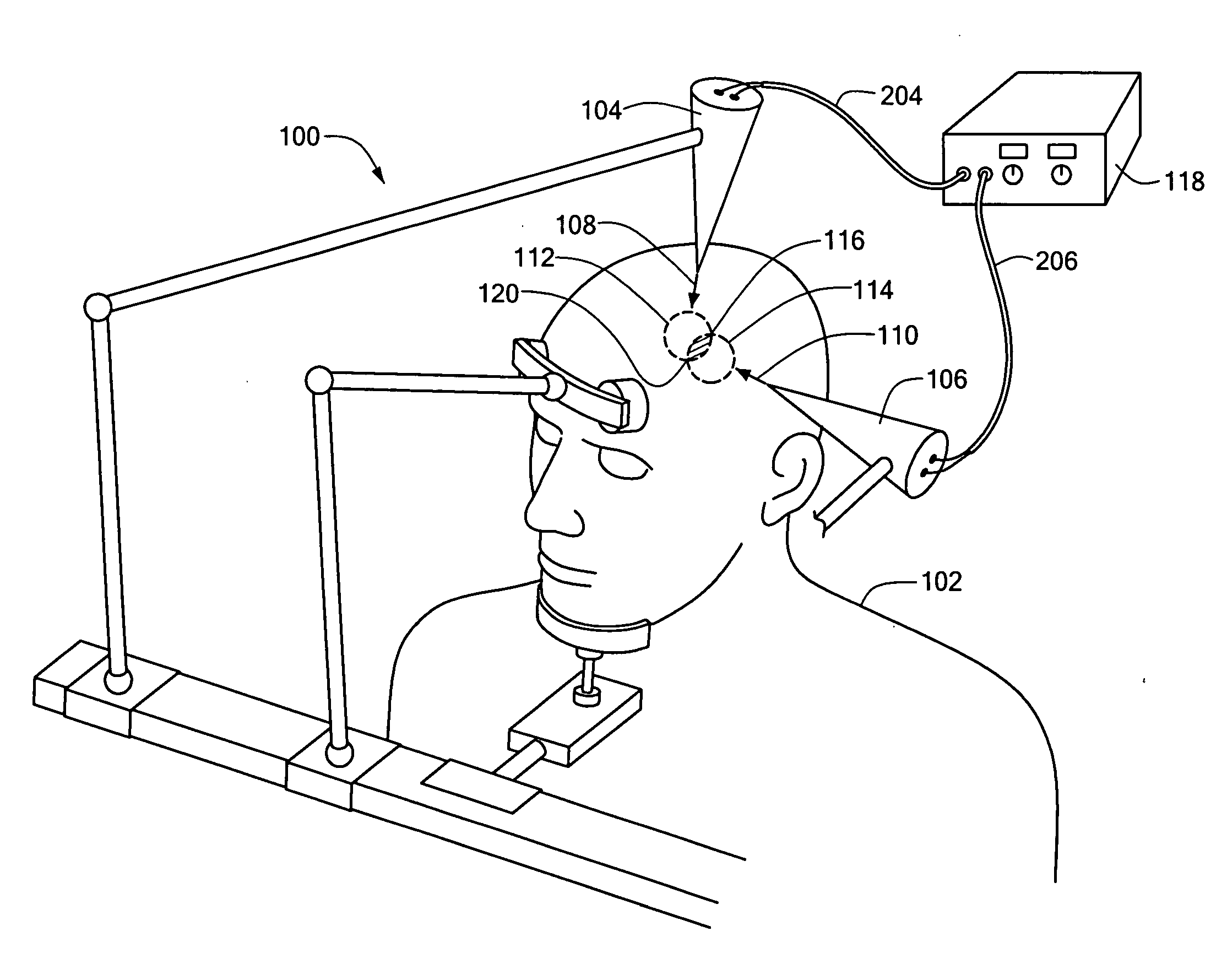
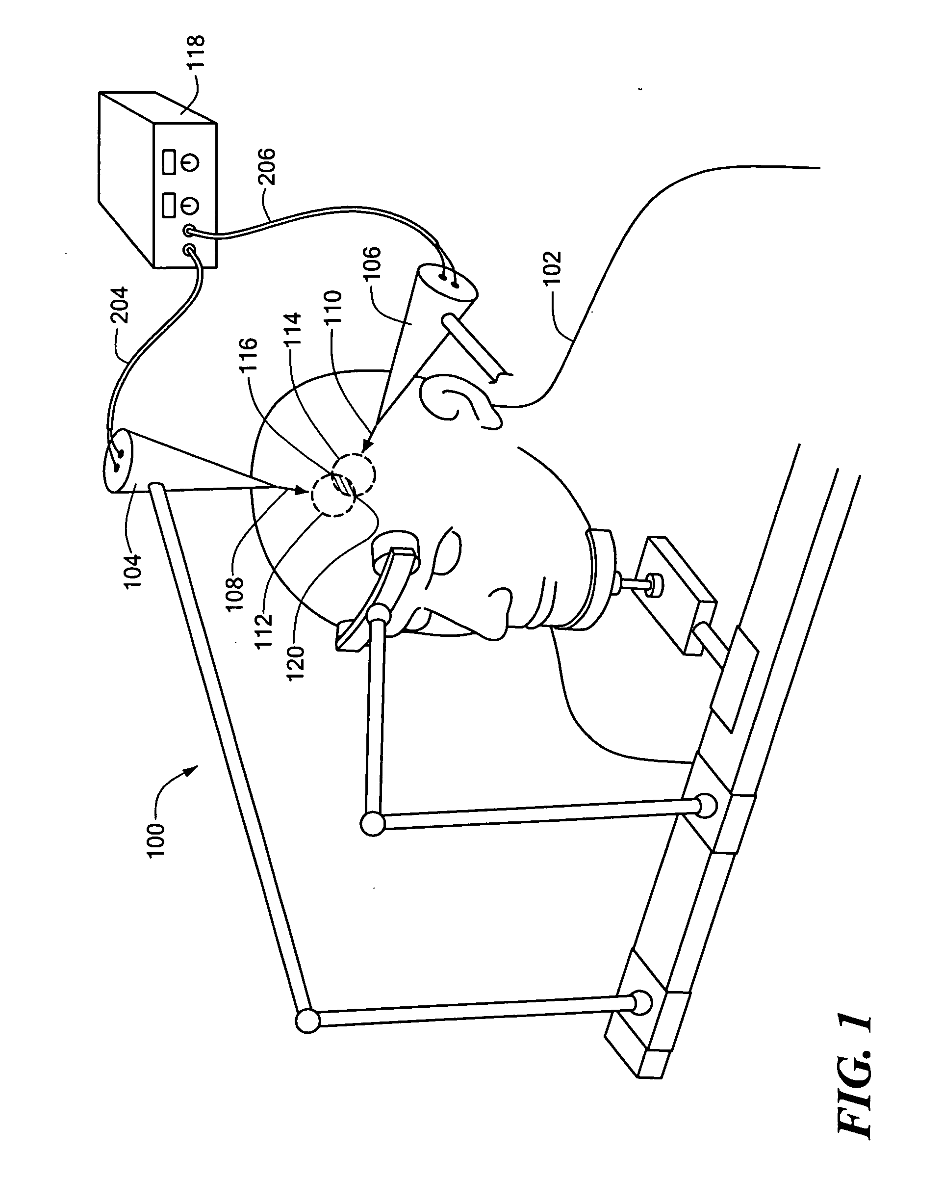
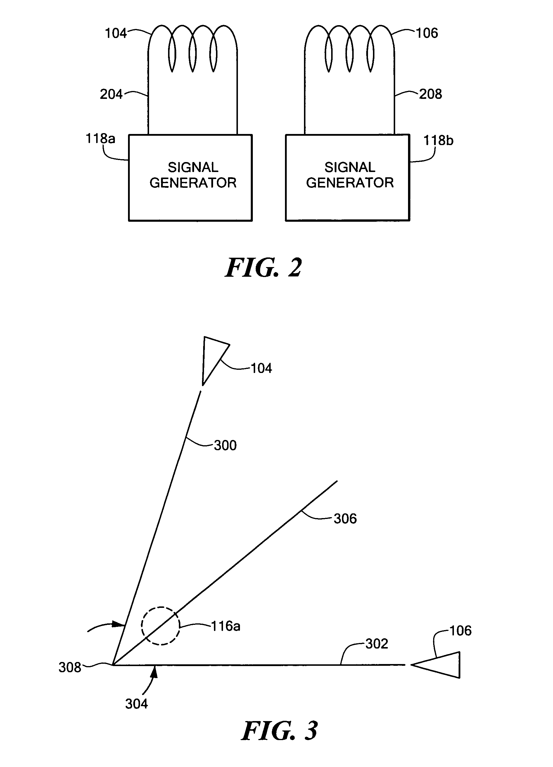
[0029] Embodiments of the present invention use at least two coils to deliver at least two time-varying magnetic fields to a body. Each magnetic field induces an electric field and electric currents in electrically conductive tissues, such as nerves or muscles, within a portion of the body. Each electric field and its currents may extend beyond its respective magnetic field, because of the conductive nature of the tissues.

[0030] The at least two magnetic fields need not necessarily intersect, however the coils are oriented such that the electric fields or currents intersect in a target region of the body. The coils are preferably driven at frequencies and amplitudes that do not directly cause significant tissue stimulation, but a beat frequency signal produced in a region where the electric fields or currents intersect (the intersection region) alternates at a frequency (the beat frequency) that stimulates excitable tissue in the target region.

[0031] In clinical or experimental co...


PUM


Abstract

At least two coils deliver at least two time-varying magnetic fields to a target region within a body. The coils are oriented such that the magnetic fields create intersecting electric fields in the target region. The magnetic fields operate at different frequencies and thus produce a beat frequency signal where the electric fields intersect. The frequencies are chosen so a time-varying electric field, or a current induced by a time-varying magnetic field, alternating at the beat frequency would stimulate excitable tissue located in the target region. Some embodiments utilize a novel coil, which includes a first conductor and at least one second conductor electrically connected to the first conductor at a point. The second conductor extends from the point of connection with the first conductor to a location spaced from the first conductor. At least a portion of the second conductor adjacent the point of connection with the first conductor is non-parallel to the first conductor.

Description

CROSS REFERENCE TO RELATED APPLICATIONS [0001] This application claims the benefit of U.S. Provisional Application No. 60 / 455,309, filed Mar. 17, 2003, the contents of which are hereby incorporated by reference herein.STATEMENT REGARDING FEDERALLY SPONSORED RESEARCH OR DEVELOPMENT [0002] (Not applicable) BACKGROUND OF THE INVENTION [0003] 1. Field of the Invention [0004] The present invention relates to electrical stimulation of tissues for therapeutic, diagnostic or experimental purposes and, more particularly, to systems that use time-varying magnetic fields to create electric fields or currents that stimulate these tissues. [0005] 2. Related Art [0006] Electric and magnetic signals are used to stimulate regions of bodies for therapeutic, diagnostic and experimental purposes. For example, motor-control regions deep within the brains of Parkinson's patients are sometimes electrically stimulated to arrest shaking (dyskinesia), and some protocols for treating depression call for elec...

Claims


Application Information

Patent Timeline
IPC IPC(8): A61N1/00A61NA61N1/40A61N2/00A61N2/02A61N2/04
CPCA61N1/40A61N2/006A61N2/02
Inventor EISENBERG, SOLOMONRMOCANU, DANIEL
Owner EISENBERG SOLOMONR
Why Eureka
Try Eureka