Apparatus for molding metals

a technology of metal molding and casting machine, which is applied in the direction of molten metal conveying equipment, chemical apparatus and processes, manufacturing tools, etc., can solve the problems of excessive scrap, high energy consumption, and limited conventional die casting procedures, so as to reduce the temperature gradient, reduce the cycle time, and reduce the thermal gradient through the thickness of the barrel

Inactive Publication Date: 2006-04-18
THIXOMAT
View PDF10 Cites 20 Cited by
  • Summary
  • Abstract
  • Description
  • Claims
  • Application Information

AI Technical Summary

Benefits of technology

[0022]The above and other objects are accomplished in the present invention by providing a novel construction where suitable frequency induction heaters are strategically positioned along at least a portion of the length of the barrel. As a result the machine experiences a decrease in the thermal gradient through the thickness of the barrel and a decrease in the cycle time for each successive shot. The coils of the suitable frequency induction heaters generate the optimum power density electromagnetic flux field to induce an electric current that flows within the barrel, liner, processed material and screw. This induced electric current directly heats the barrel, liner, processed material and screw by I2R (joule) heat generation. By specifying the location, power density and frequency of these induction heaters, it has become possible to decrease the temperature gradient through the various sections of the barrel and while also directly heating the screw and the feedstock. As a result, the temperature gradient through the barrel thickness can be a low as 0° F. after preheating, before the introduction of feedstock or during the holding time between successive shots. Contrarily, resistance heaters can heat only the outer of the barrel surface and then must conduct the heat to the material being processed. The power transferred is simply determined by the wall thickness and surface temperature. With induction, the heat is generated internally to the barrel and screw and the thermal stresses substantially reduced accordingly.
[0023]Induction electromagnetic heating generates an alternating flux field which induces an electric current to flow within the operational components of the machine (barrel, screw, and even feedstock). This current generates internal heat within these components based on the induced levels of current (power density) and the inherent electrical resistivity of the particular component. The thermal profile can be adjusted based on power density and frequency and can be programmed to provide the optimum thermal gradient to enhance productivity and process quality.
[0024]According to the present invention, the induction coils or heaters are appropriately spaced along the length of the barrel to create the desired temperature gradient along the length of the barrel for optimum melting. The present machine was designed to have a higher power density near the cold end of the machine (the feedstock inlet of the machine) to directly heat and bring the material up to temperature as rapidly as possible. In other words, the material can be heated without requiring conductive heat transfer from the heater itself and through another body or material. The heat input is then profiled along the barrel length to provide the proper power distribution to continue to add energy to the material as it is fed and moved through the barrel. In this manner it is possible to prevent liquid metal from returning to the feed throat through which the feedstock is introduced into the barrel. By limiting liquid metal at the feed throat, the present invention prevents the freezing of such liquid metal, and therefore plugging of the feed throat upon the introduction of feedstock into the barrel. Furthermore, the screw and feedstock itself can be preferentially heated to melt any solid metal plugs, should they form.
[0027]A machine according to the principles of the present invention, provided with suitable induction heating coils in zones 1 and 2 of the barrel length, enabled the production of the 4 bar tensile molding on a 16 to 20 second cycle time (a 56% decrease). This production cycle was maintained for several hours without incident. The machine ran quieter and screw retraction was smoother and quicker requiring only 5 seconds (versus 11 seconds for the 245 ton JSW machine having ceramic heaters). In addition, and as seen in the attached tables, the microstructure of the 4 bar tensile molding was refined by this invention, making for more thixotrophy and fluidity and therefore better mold filling. The α-solid phase was refined by the vigorous and fast action afforded by the influence of the low frequency heating and the resultant hot screw. As seen in the table, there is a reduction in the area, perimeter, width and height of the α-solid phase. The decrease in size and increase in roundness improved the fluidity mentioned above since fluidity is inversely proportional to the diameter times the surface area of α.
[0029]With utilization of the present invention, one preferred construction of the barrel (and liner) employs non-magnetic materials. The utilization of non-magnetic materials allows for deeper penetration by the inductive heater. It has additionally been found that the position of the screw is critical during the preheating stage. Preferably the screw is retracted during heat up, prior to feeding of the feedstock for operation, to prevent overheating of the first feedstock at the feed throat. The screw can be moved forward to enable melting of any plugs that may occur during operation. This concept substantially reduces, and possibly eliminates, thermal fatigue problems of both the barrel and the other operational components. The inductor coil design and electromagnetic coupling techniques, as well as axial position, can program the desired thermal profiles to optimize the process quality as well as the productivity objectives. The present invention can therefore provide more accurate process control and faster response time since the thermal energy is generated directly within the mechanical hardware itself.

Problems solved by technology

These conventional die casting procedures are limited in that they suffer from porosity, melt loss, contamination, excessive scrap, high energy consumption, lengthy duty cycles, limited die life, and restricted die configurations.
Furthermore, conventional processing promotes formation of a variety of microstructural defects, such as porosity, that require subsequent, secondary processing of the articles and also result in use of conservative engineering designs with respect to mechanical properties.
As further discussed below, the thermal gradient through the barrel thickness is undesirable.
This has led to increased thermal gradients throughout the barrels and previously unforeseen and unanticipated consequences.
Reviews of failed barrels has yielded information that barrels fail often as a result of the thermal stress and more particularly thermal shock in the cold section or end of the barrels.
During use of a thixotropic material molding machine as described above, the solid material feedstock, which has been seen in pellet and chip forms, is fed into the barrel while at ambient temperatures, approximately 75° F. Being long and thick, the barrels of these machines are, by their very nature, thermally inefficient for heating a material introduced therein.
Therefore, the energy level that is generated at the outside surface of the barrel, has to be high enough to sufficiently accelerate the energy flow to get uniform heating of the barrel, which therefore slows down the process and causes thermal fatigue of the barrel.
Additionally, these resistance heaters, because of the thermal cycling they undergo, are also highly subject to thermal fatigue and frequent replacement.
Another major problem is that the resistance heaters cannot couple thermal energy directly in the screw.
As a result there are substantial thermal criteria in this arrangement which impact productivity and response to the thermal dynamics of handling incoming cold feedstock.
Because of the significant cycling of the thermal gradient in the barrel, the barrel experiences thermal fatigue and shock.
This has been found to cause cracking in the barrel and in the barrel liner in as little time as 30 hours.
Once the barrel liner has become cracked, magnesium can penetrate the liner and attack the barrel.
Both the cracking of the barrel and the attacking of the barrel by magnesium will contribute to the premature failure of the barrels.

Method used


Image

  • Apparatus for molding metals
  • Apparatus for molding metals
  • Apparatus for molding metals

Examples


Embodiment Construction

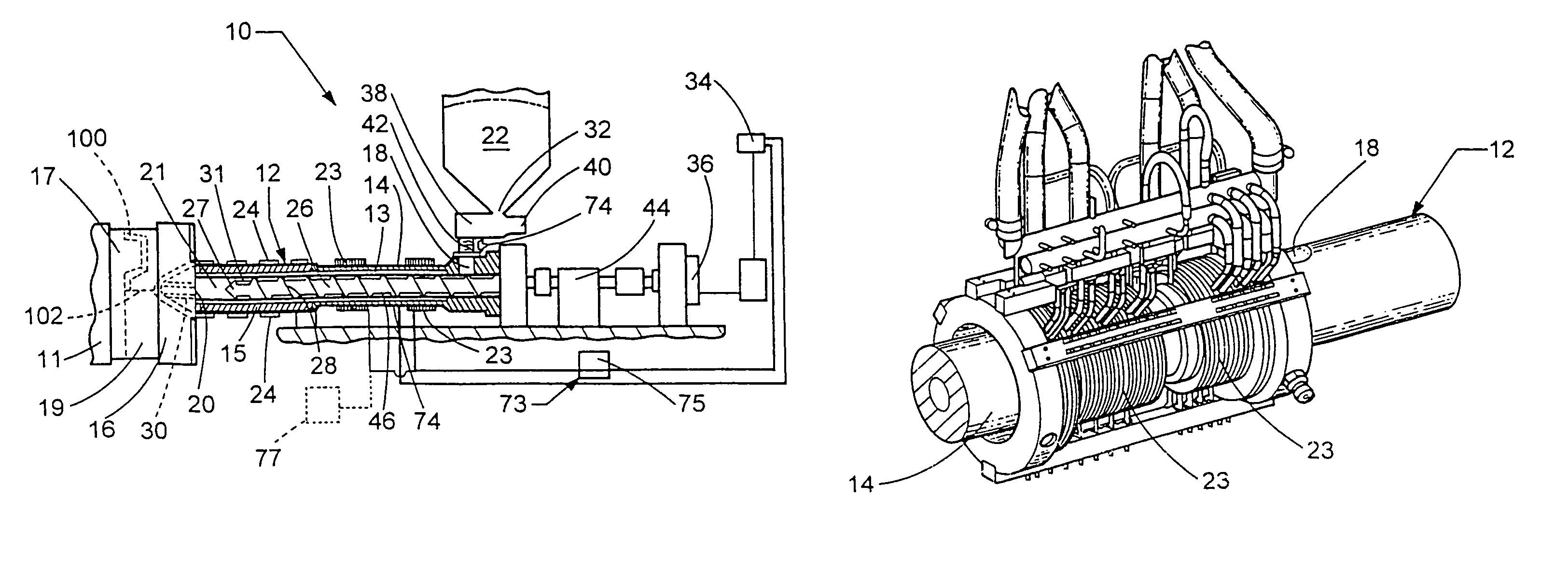
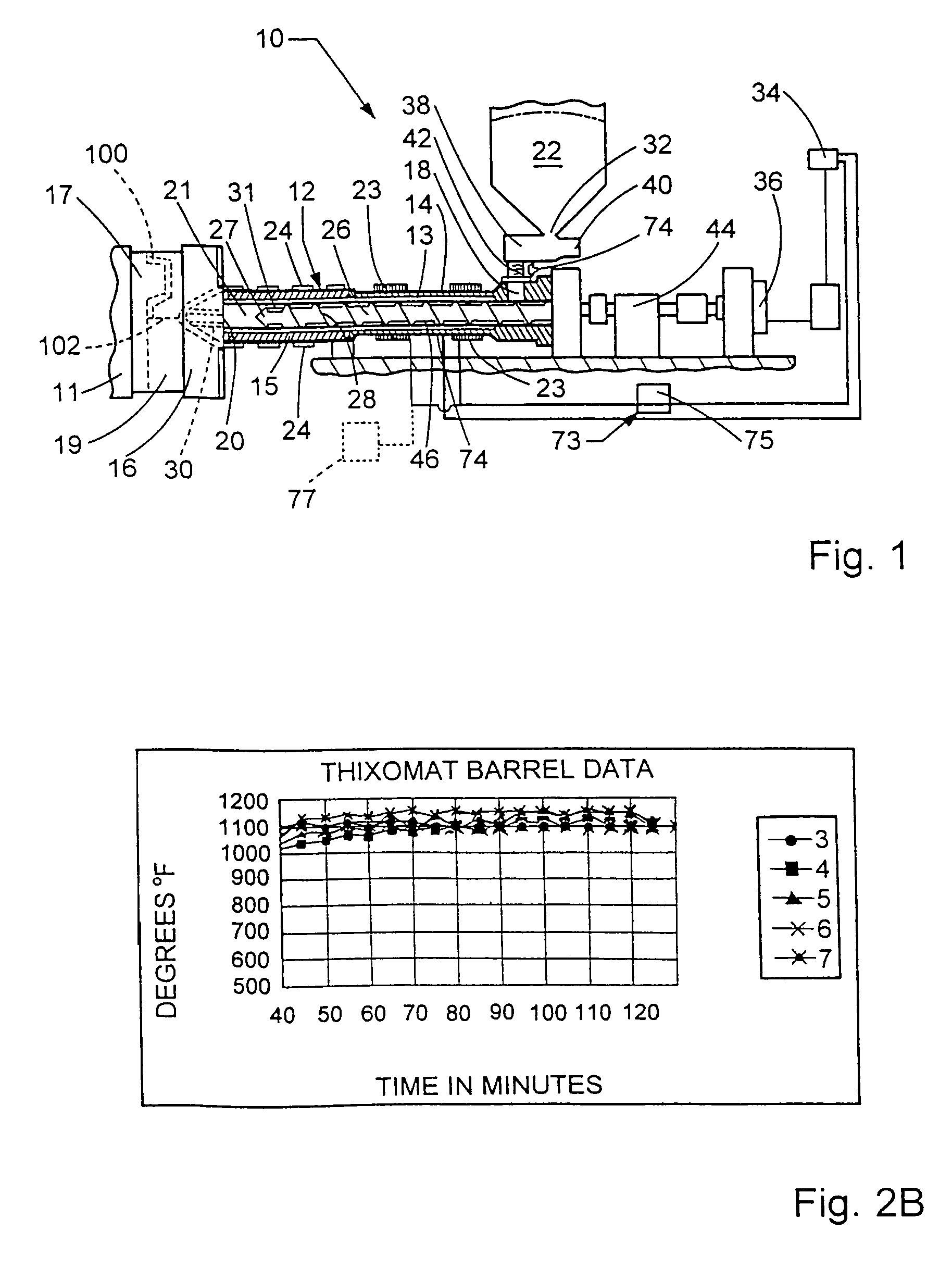
[0040]Referring now to the drawings, a machine or apparatus for processing a metal material into a thixotropic state or molten state and molding the material to form molded, die cast, or articles for forging according to the present invention is generally illustrated in FIG. 1 and designated at 10. Unlike typical die casting or forging machines, the present invention is adapted to use a solid state feedstock of a metal or metal alloy (hereinafter just “alloy”). This eliminates the use of a melting furnace, in die casting processes, along with the environmental and safety limitations associated therewith. The present invention is illustrated as accepting feedstock in a chipped or pelletized form. These feedstock forms are preferred, but other forms may be used. The apparatus 10 transforms the solid state feedstock into a semisolid, thixotropic slurry or liquid which is then formed into an article of manufacture by either injection molding or die casting.

[0041]The apparatus 10, which ...


PUM

PropertyMeasurementUnit
frequencyaaaaaaaaaa
temperatureaaaaaaaaaa

Abstract

An apparatus for molding a metal material. The apparatus includes a vessel with portions defining a passageway through the vessel. An inlet is located toward one end and a member or agitation means is located within the passageway. A plurality of heaters are located a length of the vessel. The first of the heaters is located immediately downstream of the inlet and is a low frequency induction coil heater whereby the temperature gradient through the vessel's sidewall is minimized.

Description

FIELD OF THE INVENTION[0001]This application is a divisional application of prior U.S. application Ser. No. 09 / 861,250, filed May 18, 2001 (now abandoned) and claims domestic priority thereto under 35 U.S.C. §§ 120, 121.[0002]The present invention generally relates to metal molding and casting machines. More specifically, the invention relates to a metal molding machine adapted for quicker heat up times, faster cycle times and reduced thermal stresses in the machine.BACKGROUND OF THE INVENTION[0003]This invention relates to an apparatus for molding metals into articles of manufacture. More specifically, the present invention relates to an apparatus of the above type configured to increase thermal efficiency and increase through-put while decreasing thermal gradients and the resultant stresses.[0004]Metal compositions having dendritic structures at ambient temperatures conventionally have been melted and then subjected to high pressure die casting procedures. These conventional die c...

Claims


Application Information

Patent Timeline
Patent Type & Authority Patents(United States)
IPC IPC(8): B22D17/00B22D17/20B22D17/30B22D35/06
CPCB22D17/007B22D35/06B22D17/2038Y10S164/90
Inventor AKERS, RONVINING, RALPH E.WALUKAS, D. MATTHEWDECKER, RAYMOND F.PEDDER, CHRIS
Owner THIXOMAT
Why Eureka
Try Eureka