Camshaft adjuster with play-free locking

a technology of camshaft adjuster and play-free locking, which is applied in the direction of couplings, rotary or oscillating piston engines, applications, etc., can solve the problems of hardly possible further rattling noise and still subject to the arresting process, and achieve the effect of easy production and small rattling nois

Inactive Publication Date: 2006-09-14
HYDRAULIK RING
View PDF7 Cites 17 Cited by
  • Summary
  • Abstract
  • Description
  • Claims
  • Application Information

AI Technical Summary

Benefits of technology

[0008] It is obvious that the professional world has for a long time been searching for a locking pin or bar which, during operation, even at high angle of rotation velocities, is securely caught

Problems solved by technology

However this arresting process is still subject to play.
I

Method used


Image

  • Camshaft adjuster with play-free locking
  • Camshaft adjuster with play-free locking
  • Camshaft adjuster with play-free locking

Examples


Embodiment Construction

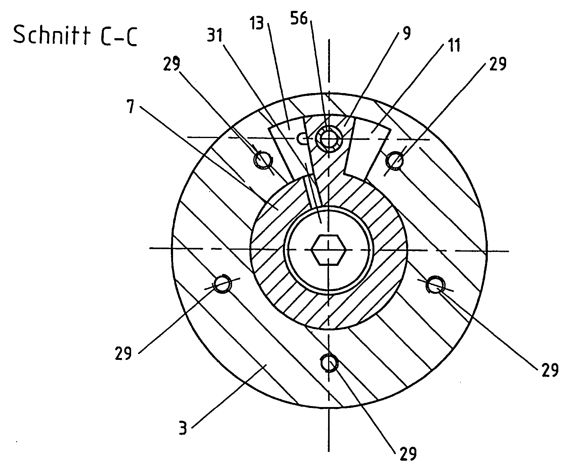
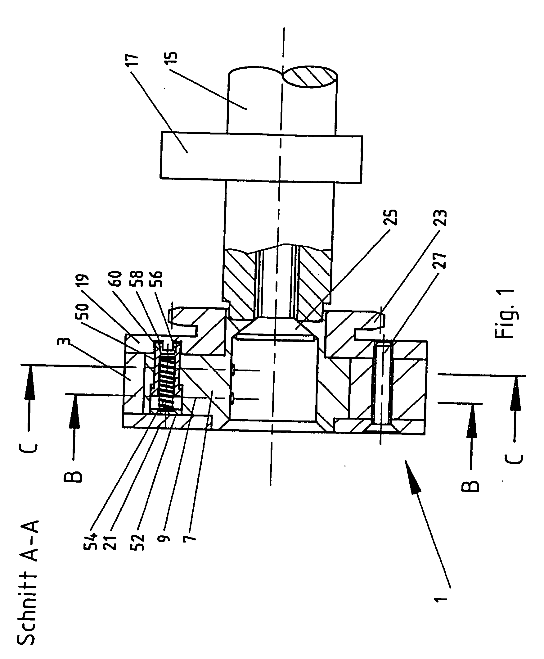
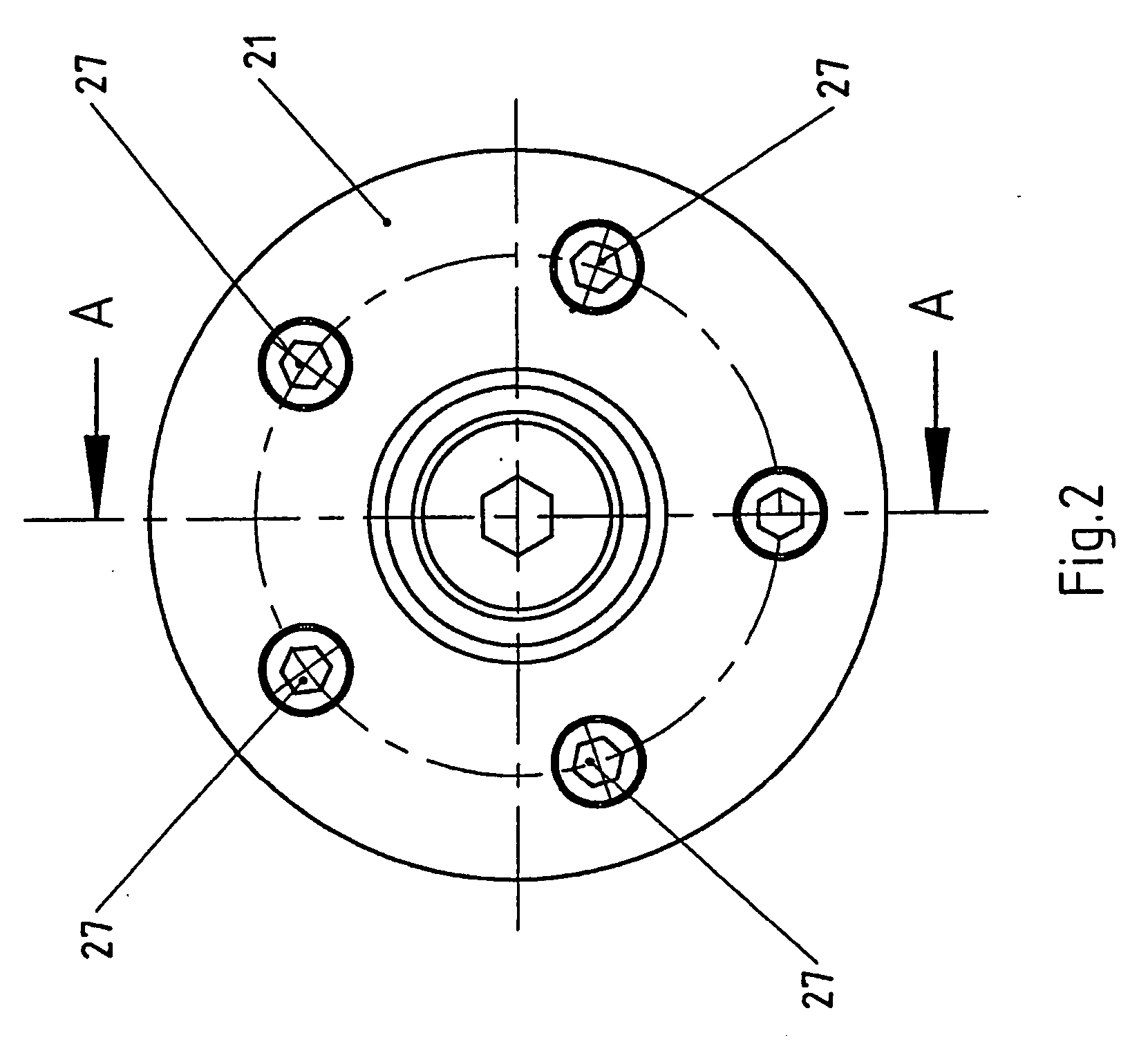
[0027]FIG. 2 is a plan view onto one side of a camshaft adjuster which is outlined in FIG. 1 with indicated camshaft. Further sections can be seen in FIG. 3 and FIG. 4. The camshaft adjuster 1 is engaged with a shaft 15, on which a cam 17 is represented. FIG. 1 shows that the camshaft adjuster can be connected both by a connecting screw 25 and by a non-positive engagement between the shaft 15 and the sprocket wheel 23. The cover 21 of a camshaft adjuster 1 is held together by fastening means such as clamping screws 27. The housing 19 and the cover 21 close off hollow spaces which are represented as hydraulic chambers 11 and 13 in FIGS. 3 and 4. The chambers 11, 13 can be supplied with a hydraulic medium through oil ducts 31. The clamping screws 27 pass through screw guides 29 which are provided in the stator 3 of the camshaft adjuster 1. The screw guides 29 of the stator 3 may advantageously lie in webs 5. The rotor 7, which may have one or more blade(s) 9, is located in the stator ...


PUM

PropertyMeasurementUnit
Thicknessaaaaaaaaaa
Diameteraaaaaaaaaa
Heightaaaaaaaaaa

Abstract

Camshaft adjusters according to the swivel motor principle may be provided with a bar which arrests the rotor in a position relative to the stator. A bar according to the invention is provided with two portions, between which a change of power transmission takes place during the arresting process.

Description

CROSS REFERENCE [0001] This application claims priority to German application number 10 2005 004 281, filed Jan. 28, 2005. BACKGROUND OF THE INVENTION [0002] The invention relates to a camshaft adjuster with play-free locking according to the preamble of claim 1. [0003] There are numerous camshaft adjusters. Apart from helically toothed camshaft adjusters, camshaft adjusters according to the swivel motor principle are widely used. As a rule swivel motor camshaft adjusters have a housing which is also called a stator and in which a rotor with an arbitrary number of blades can move. Chambers for accommodating a hydraulic fluid such as, for example, a motor oil, are formed between webs of the stator and the blades of the rotor. The freedom of motion between the rotor and the stator may optionally be limited or impeded by a bar. Bars of this kind or locking pins are frequently spring-biased. The bar is only moved into an unlocked position when a spring force is overcome. A hydraulic pre...

Claims


Application Information

Patent Timeline
IPC IPC(8): F01L1/34
CPCF01L1/3442F01L2001/34453F01L2001/34469B29D28/00B26F1/18B26F1/24B29C65/04B29C66/02242
Inventor SCHWEIZER, STEFFEN
Owner HYDRAULIK RING
Why Eureka
Try Eureka