Power unit

a power unit and power supply technology, applied in the field of power units, to achieve the effect of simple operation and shutting down the operation of the power uni

Inactive Publication Date: 2006-09-14
HONDA MOTOR CO LTD
View PDF4 Cites 39 Cited by
  • Summary
  • Abstract
  • Description
  • Claims
  • Application Information

AI Technical Summary

Benefits of technology

[0010] According to the invention having the above-described characteristics, the power unit can be operated in a mode selected according to an operation of the mode selection switch during a power failure. For example, when a household is gone out with the interconnected operation mode has selected, operation of the power unit is automatically shut down when a power failure occurs while the household is gone out. On the other hand, the household has selected the isolated operation mode while they are at home, an emergency power supply can be secured by an isolated operation during a power failure. Accordingly, it is possible to flexibly correspond to an electric power usage pattern, such that there is no inconvenience in most situations even if the power unit shuts down during a power failure while the household is not stayed and the household often wishes to immediately relay and operate in-use electric appliances by an emergency power supply during a power failure while at home, by operating the mode selection switch.
[0011] Even in the isolated operation during a power failure, when electric power supply becomes no longer necessary, it is possible to shut down operation of the power unit by a simple operation to select the interconnected operation mode with the mode selection switch. In contrast to this, when an electric power demand arises when operation of the power unit has been shut down during a power failure, it is possible to start operation of the power unit by selecting the isolated operation mode with the mode selection switch.
[0012] When the power unit is a constituent part of a cogeneration unit, by manually switching the mode selection switch according to not only whether there is an electric power demand but also whether there is a heat demand, it is possible to flexibly make the cogeneration unit available or unavailable regardless of being in a power failure.

Problems solved by technology

However, this causes an inconvenience such that the cogeneration unit being a power generating installation specially owned cannot be used in such an emergency as a power failure.

Method used


Image

  • Power unit
  • Power unit
  • Power unit

Examples


Embodiment Construction

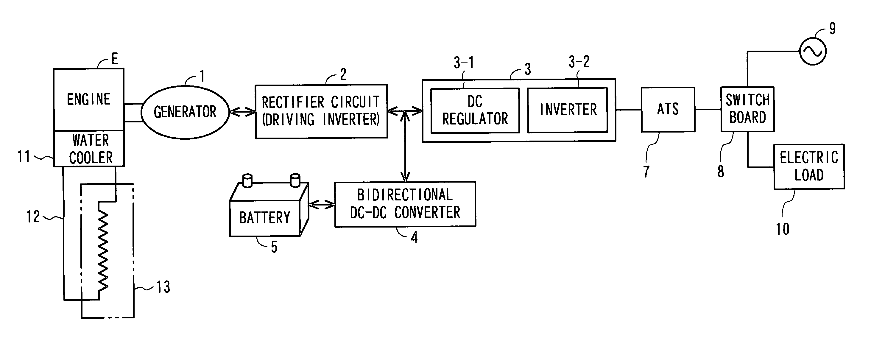
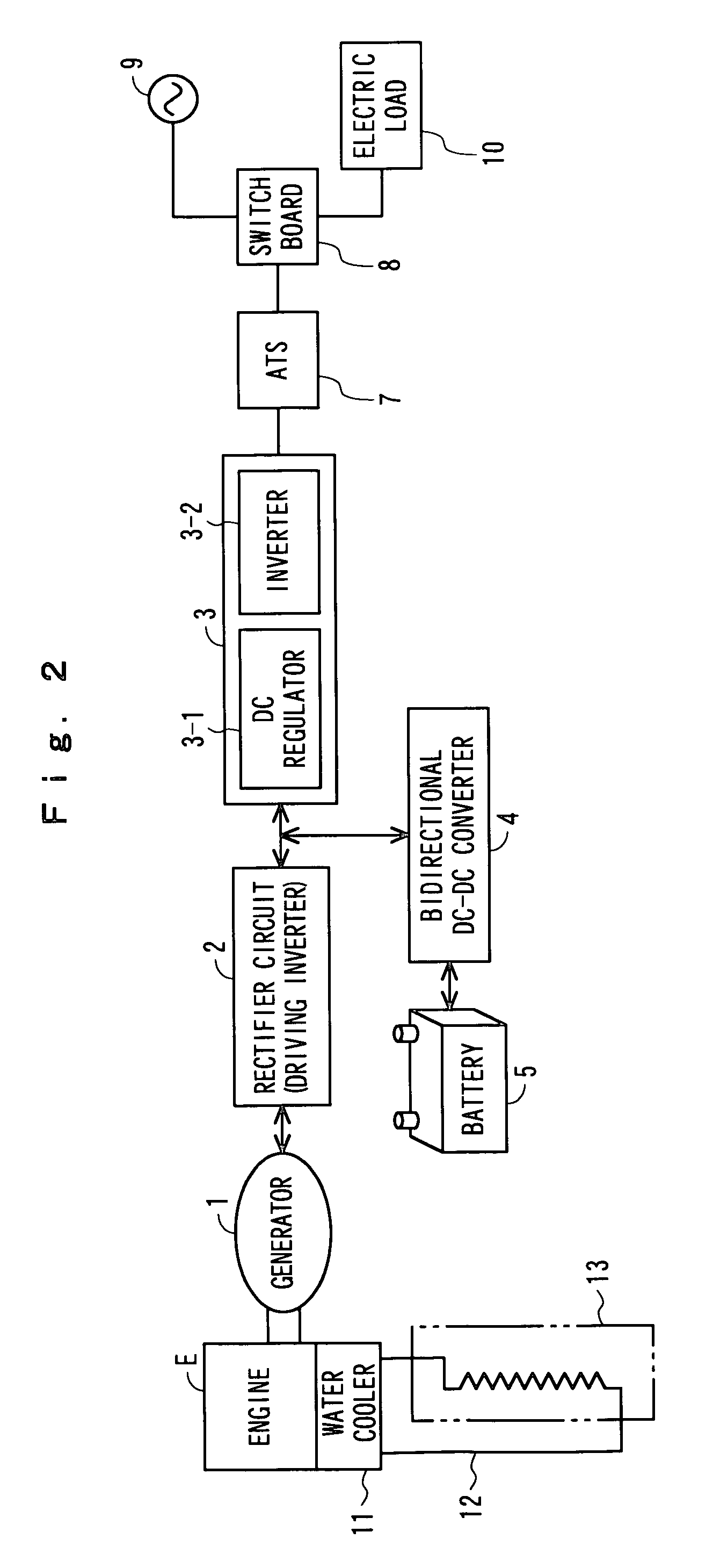
[0021] Hereinafter, an embodiment of the present invention will be described in detail with reference to the drawings. FIG. 2 is a block diagram showing a configuration of a cogeneration unit, being an example of the power unit, provided by interconnecting an engine generator with a commercial power system. In FIG. 2, a generator 1 is a 3-phase multipolar magnet-type engine driven generator where a rotor is driven by an engine E and generates an alternating-current power according to the number of engine revolutions. The generator 1 also serves as an electric motor that can also operate as an electric starter motor for the engine E. The engine E is, for example, a gas engine using town gas as a fuel and is provided with an electronic governor that controls to converge the number of revolutions to a target number of revolutions.

[0022] A rectifier circuit 2 has a bridge-connected rectifying device (unillustrated) and full-wave rectifies an output from the generator 1. Switching eleme...


PUM


Abstract

A system interconnection control section 7 interconnects and parallels off an output from a generator 1 with a system 9, and supplies an output from the generator 1 to a load 10. A selection switch 24 that selects operation modes of the generator 1 is provided. The operation modes are an interconnected operation mode to shut down operation of the generator 1 and an isolated operation mode to operate the generator 1 after disconnecting the output from the generator 1 from the system, when a power of the system 9 has been stopped. During a power failure, the selection switch 24 is switched to select a start and a shutdown of an isolated operation.

Description

BACKGROUND OF THE INVENTION [0001] 1. Field of the Invention [0002] The present invention relates to a power unit such as a small-sized cogeneration unit, and particularly, to a power unit that is capable of an isolated or independent operation when a commercial power system with which a power output from the power unit has been interconnected was cut off. [0003] 2. Description of the Related Art [0004] In recent years, the need to protect the global environment has been trumpeted, and a cogeneration unit being a private power generating installation that generates power and supplies hot water using an engine such as a gas engine using town gas or the like as fuel as a power source has been drawing great attention. With this type of cogeneration unit, since it is often the case that a heat energy generated as a result of power generation cannot be consumed simultaneously with electric power, from the standpoint of thoroughly using this heat energy, a heat demand-priority unit that p...

Claims


Application Information

Patent Timeline
Patent Type & Authority Applications(United States)
IPC IPC(8): H02J9/00
CPCH02J9/062H02J9/066H02J9/08Y02E20/14
Inventor HASHIMOTO, SHOJISHIMIZU, MOTOHIRO
Owner HONDA MOTOR CO LTD
Why Eureka
Try Eureka