
Automatic darkening filter with offset polarizers

Active Publication Date: 2006-09-14
3M INNOVATIVE PROPERTIES CO
View PDF54 Cites 37 Cited by
  • Summary
  • Abstract
  • Description
  • Claims
  • Application Information

AI Technical Summary

Benefits of technology

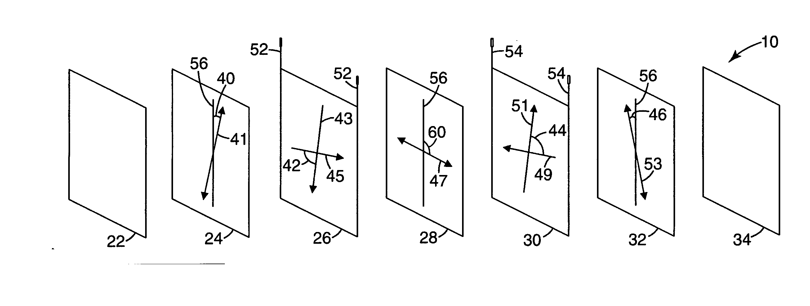
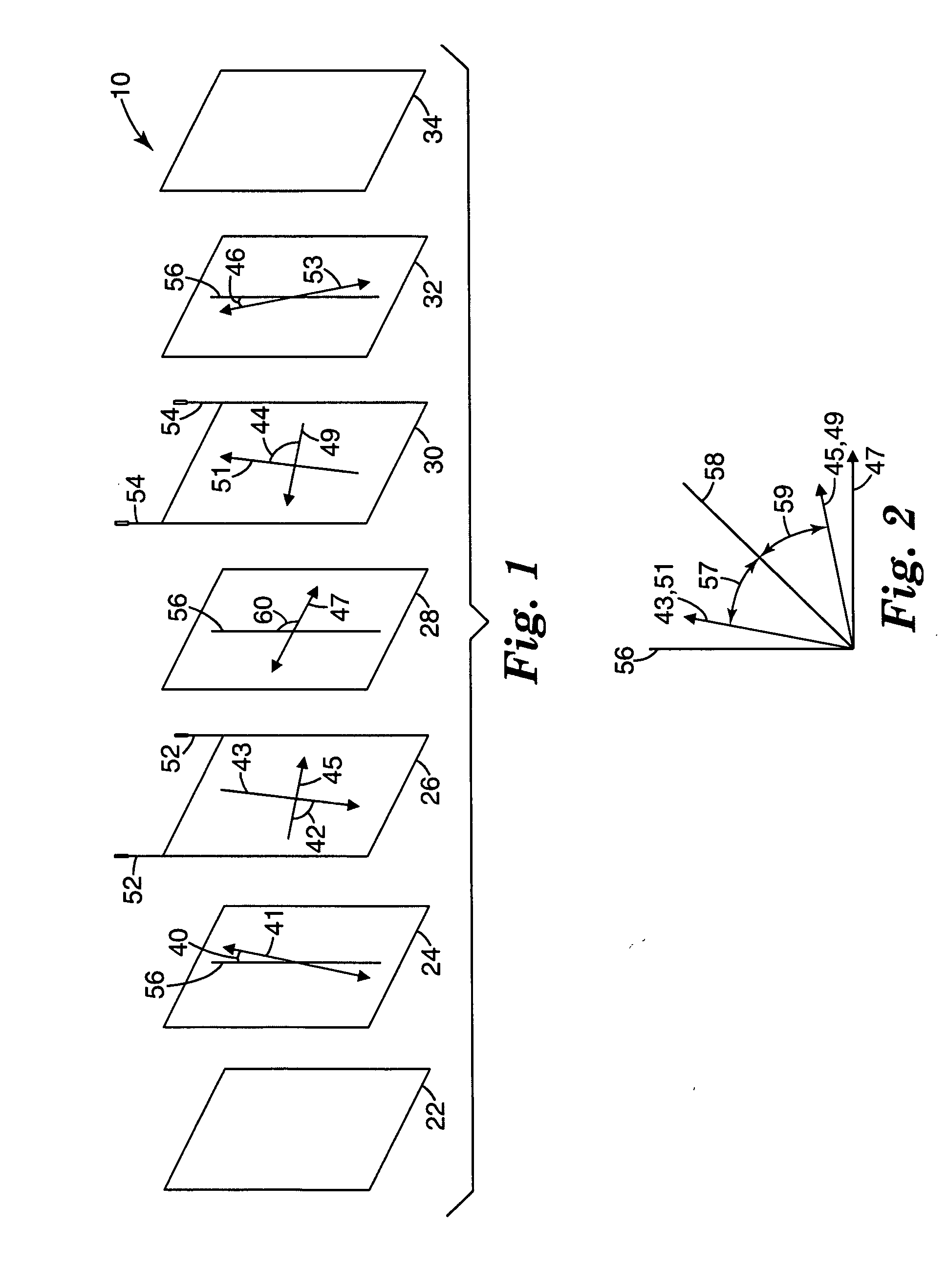
[0008] The present invention differs from known automatic darkening filters in that at least one of the first and third polarizers are offset from a normal axis to a polarization orientation of the second polarizer. By offsetting the polarization orientation of at least one of the first or third polarizers, a more homogeneous shade in the dark state may be obtained. Offsetting the polarization orientation of one or both of the first or third polarizers allows a small amount of light to leak through the filter, causing an overall softening effect that reduces variations in shade as viewed through the filter. By reducing variations in shade, visibility through the filter may be improved. Improvements in visibility can be particularly beneficial to welders because they need to see in detail the objects on which they are working.

Problems solved by technology

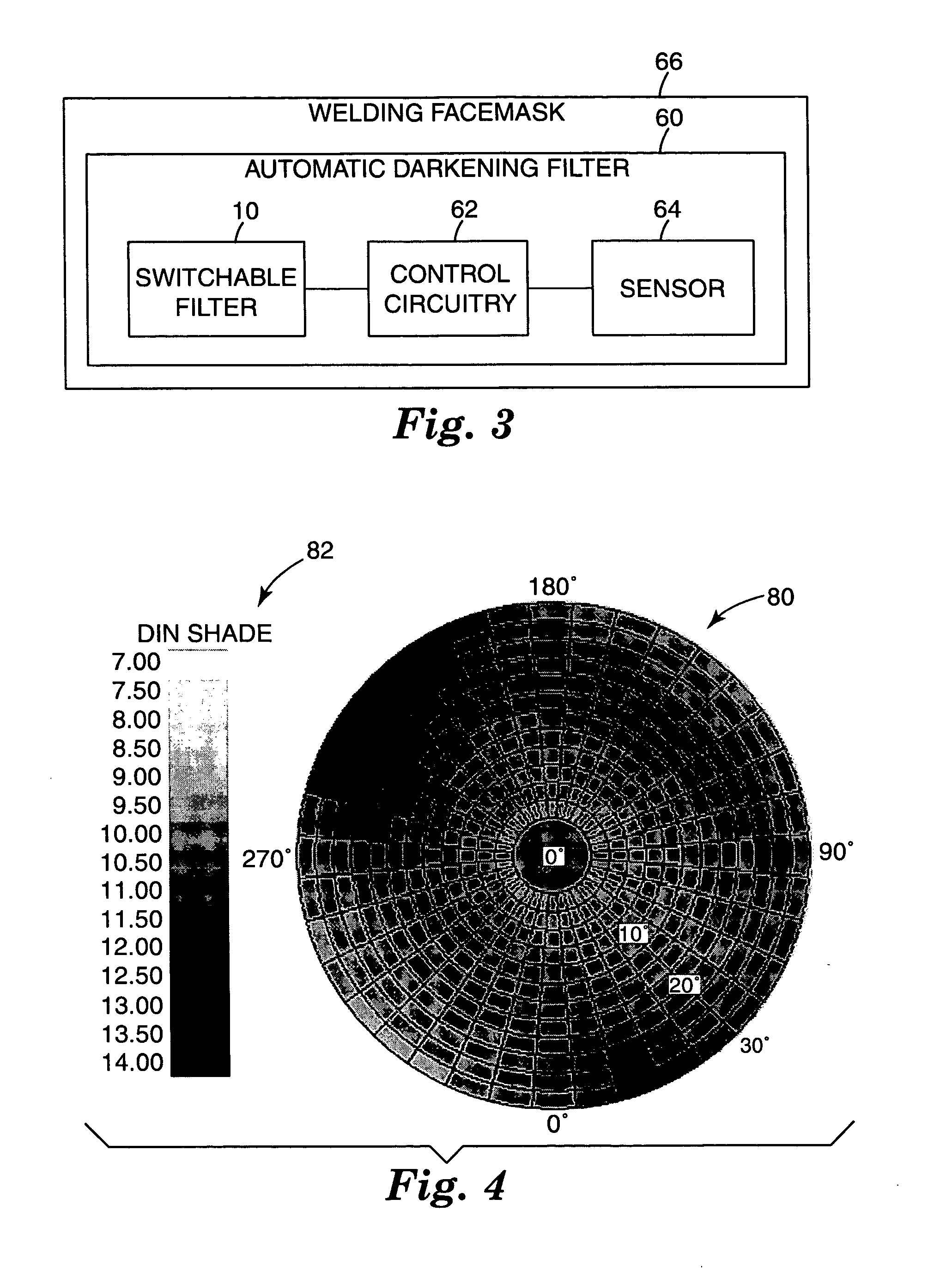
Conventional filters have one particular drawback, namely, the filter effect of the liquid crystal layers is angularly dependent.
In other words, the viewing area as seen by the user may appear to darken unevenly.

Method used


Image

  • Automatic darkening filter with offset polarizers
  • Automatic darkening filter with offset polarizers
  • Automatic darkening filter with offset polarizers

Examples


Embodiment Construction

[0014]FIG. 1 is an exploded view of an example embodiment of a switchable filter construction 10 that is useful for automatic darkening filter applications. The outermost component is an interference filter 22, which filter functions in part to eliminate UV light and IR light and limits the wavelength range. Filter 10 also includes a first polarizing filter 24, a first optically rotating liquid crystal cell 26, a second polarizing filter 28, a second optically rotating liquid crystal cell 30, and a third polarizing filter 32. The arrangement may optionally also include a so-called guest-host-cell 34.

[0015] First and second liquid crystal cells 26 and 30 are low twist liquid crystal cells. As used in this document, the term “low twist” means having a twist angle of less than 90 degrees. For example, at least one of first and second liquid crystal cell 26 or 30 has a twist angle of less than 90 degrees, typically zero or 1 to 89 degrees. More specifically, the twist angle of at least...


PUM


Abstract

A protective automatic darkening filter construction 10 includes two low twist liquid crystal cells 26, 30 interspersed between a series of offset polarizers 24, 28, 32. The resulting construction provides improved homogeneity in the dark state as viewed by the user over a large viewing angle. By reducing variations in shade, visibility through the filter may be improved.

Description

[0001] The present invention pertains to an automatic darkening liquid crystal protective shield or filter that can be used on a welding helmet to filter light incident from a welder's torch. BACKGROUND [0002] Automatic darkening liquid crystal protective shields, also known as automatic darkening filters, or ADFs, are often constructed from a combination of polarizing filters and layers of liquid crystals. Examples of such filters are described in U.S. Pat. Nos. 6,097,451 and 5,825,441, both to Hornell and Palmer. [0003] The ADFs change from a light (transparent) state to a darker (nearly opaque) state in response to a control signal. For applications like welding where protection from intense levels of incident light is desired, the filters are normally mounted in a facemask, and the control signal is initiated by incident light from the welding arc. The incident light strikes a detector on the welding helmet which in turn sends a signal to the ADF. In this way, the filter is clea...

Claims


Application Information

Patent Timeline
IPC IPC(8): G02F1/1335
CPCA61F9/067G02F1/133528G02F1/13471G02F2001/133531G02F2001/1398G02F1/133531G02F1/1398G02B5/30G02F1/1337
Inventor MAGNUSSON, KRISTINA M.JAREFORS, KENNETHDAHLIN, PER-OLAV
Owner 3M INNOVATIVE PROPERTIES CO
Learn More