Method of producing elliptically polarizing plate and image display using the elliptically polarizing plate

a technology of elliptically polarizing plates and image displays, applied in the direction of polarizing elements, instruments, optics, etc., can solve the problems of high cost and long time, film has problems in cost, and cannot exhibit the desired optical characteristics (such as the functions of /4 plates) over a wide wavelength range, so as to achieve no waste, high production efficiency, and low cost

Inactive Publication Date: 2006-09-14
NITTO DENKO CORP
View PDF2 Cites 14 Cited by
  • Summary
  • Abstract
  • Description
  • Claims
  • Application Information

AI Technical Summary

Benefits of technology

[0025] According to the present invention, the slow axis of the first birefringent layer which can function as a λ / 2 plate can be set in any desired directions, and thus along polarizing film (polarizer) stretched in a longitudinal direction (that is, a film having an absorption axis in a longitudinal direction) can be used. In other words, a long first birefringent layer formed on a long substrate which has been subjected to the alignment treatment at a predetermined angle with respect to its longitudinal direction, a long transparent protective film and a long polarizing film (polarizer) may be continuously attached together while the respective longitudinal directions being arranged in the same direction (by so-called roll to roll). Alternatively, a long first birefringent layer formed on a long substrate which has been subjected to the alignment treatment at a predetermined angle with respect to its longitudinal direction and a laminate having a long polarizing film (polarizer) and a long transparent protective film may be continuously attached together by roll to roll. Thus, an elliptically polarizing plate can be obtained at very high production efficiency. According to the method of the present invention, the transparent protective film or the polarizer need not be cut out obliquely with respect to its longitudinal direction (stretching direction) for lamination. As a result, angles of optical axes do not vary with respect to every cut-out film, resulting in an elliptically polarizing film without variation in quality with respect to every product. Further, no wastes are produced by cutting of the film, and the elliptically polarizing plate can be obtained at low cost and production of a large polarizing plate is facilitated. Furthermore, according to an embodiment of the present invention, the second birefringent layer is easily formed by laminating the polymer film on a surface of the first birefringent layer. Long sides of the polymer film and the first birefringent layer may be continuously attached together, so as to obtain the second birefringent layer on the first birefringent layer. Thus, an elliptically polarizing plate can be obtained at very high production efficiency. Since the elliptically polarizing plate may be obtained by using so-called roll to roll attachment, adhesiveness between adjacent layers (films) can be very excellent. Furthermore, according to the present invention, the third birefringent layer having a refractive index profile of nz>nx=ny is used in combination with the λ / 4 plate and the λ / 2 plate. Therefore, a broadband and wide viewing angle elliptically polarizing plate with excellent properties even in an oblique direction, and an image display using the same can be obtained.

Problems solved by technology

Thus, the λ / 4 plate has a problem in that it cannot exhibit desired optical characteristics (such as functions of the λ / 4 plate) over a wide wavelength range.
However, such a film has problems in cost.
In the case where a film is cut out and then attached as described above, angles between optical axes may vary with respect to every cut-out film, for example, which may result in problems of variation in quality with respect to every product and production requiring high cost and long time.
Further problems include increased waste by cutting out of the films, and difficulties in production of large films.
However, the method has a problem in that the adjustment involves difficulties.
Further, an circularly polarizing plate including a combination of a polarizing film, a λ / 4 plate, and a λ / 2 plate has another problem.
In many cases, satisfactory circularly polarizing function cannot be obtained in an oblique direction due to thickness direction retardation inherent in the TAC film.

Method used


Image

  • Method of producing elliptically polarizing plate and image display using the elliptically polarizing plate
  • Method of producing elliptically polarizing plate and image display using the elliptically polarizing plate
  • Method of producing elliptically polarizing plate and image display using the elliptically polarizing plate

Examples


example 1

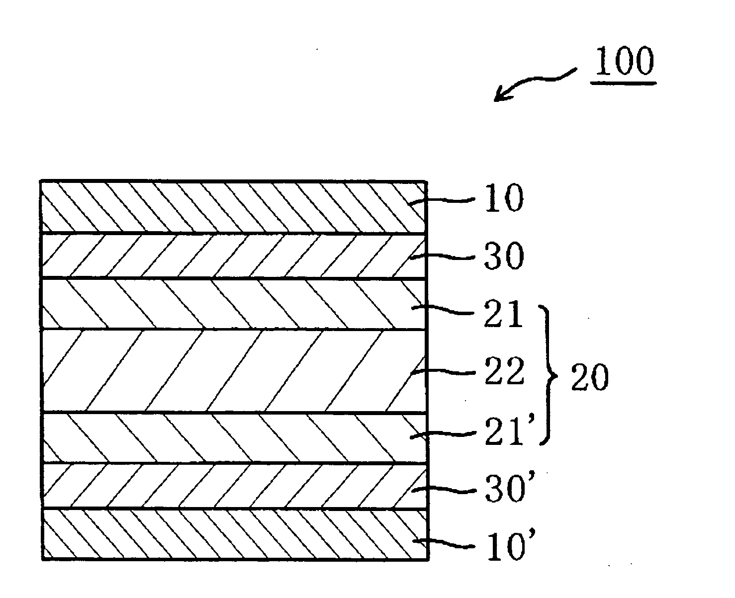
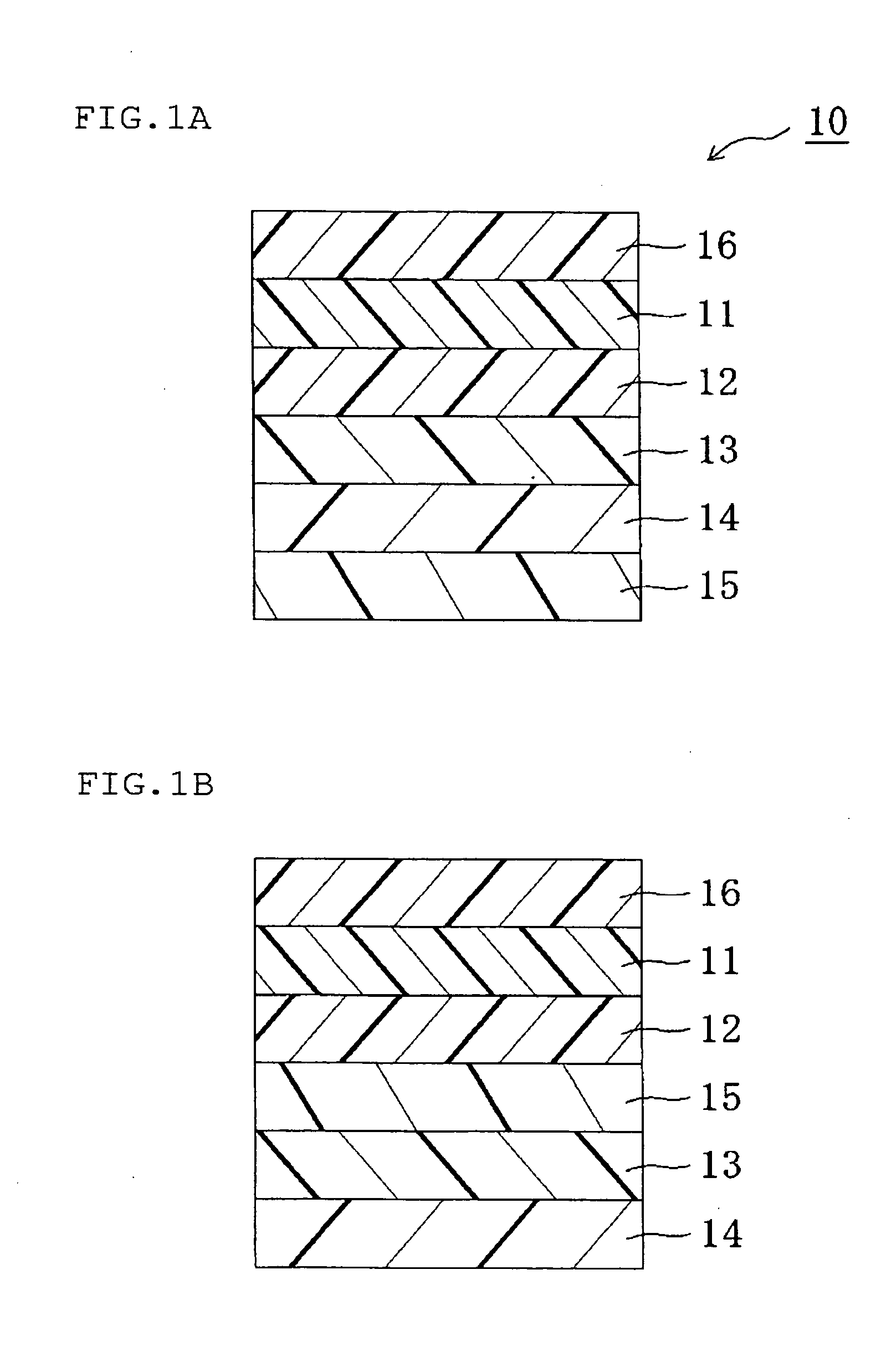
I. Preparation of Elliptically Polarizing Plate as Shown in FIG. 1A

I-a. Alignment Treatment for Substrate (Preparation of Alignment Substrate)

[0167] Substrates were subjected to alignment treatment, to thereby prepare alignment substrates.

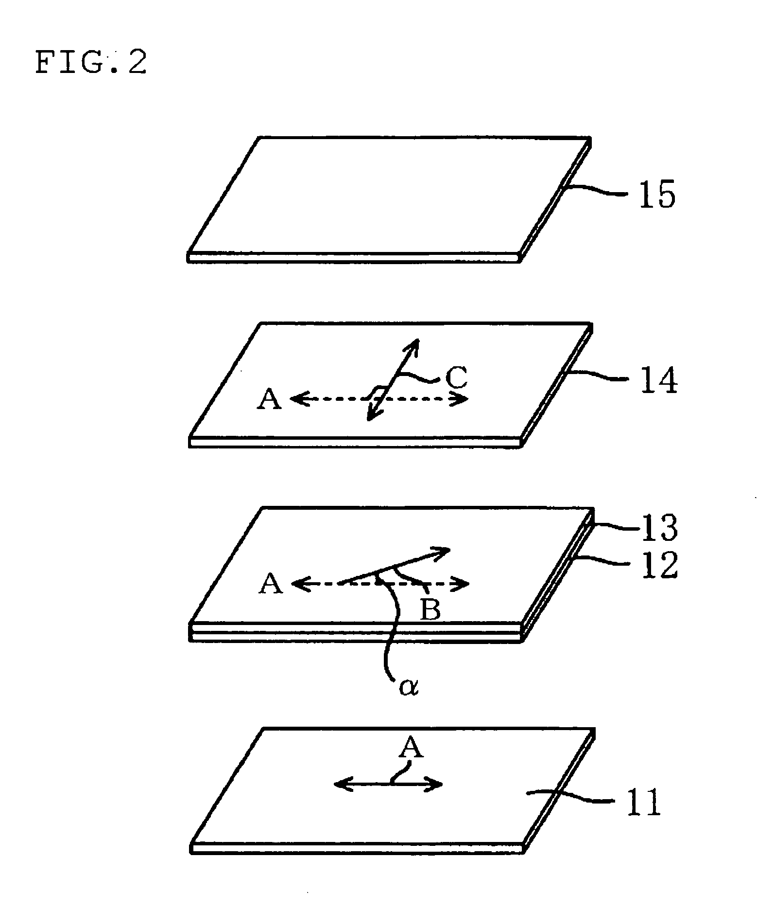
[0168] Substrates (1) to (6): The surface of a polyethylene terephthalate (PET) film (thickness of 50 μm) was subjected to rubbing at a rubbing angle shown in Table 1 by using a rubbing cloth, to thereby form each of alignment substrates.

TABLE 1SubstrateRubbing angle (angle α)(1)13°(2)−13°(3)23°(4)−23°(5)33°(6)−33°

I-b. Preparation of First Birefringent Layer

[0169] 10 g of polymerizable liquid crystal (Paliocolor LC242, trade name; available from BASF Aktiengesellschaft) exhibiting a nematic liquid crystal phase, and 3 g of a photopolymerization initiator (IRGACURE 907, trade name; available from Ciba Specialty Chemicals) for the polymerizable liquid crystal compound were dissolved in 40 g of toluene, to thereby prepare a liquid crystal comp...

example 2

II. Production of Elliptically Polarizing Plate as Shown in FIG. 1B

[0179] The same polarizer, protective layer, laminate of the first birefringent layer and the substrate, second birefringent layers (al) to (a7) and (b1) to (b2), the third birefringent layers (C1) to (C4) respectively formed on the substrate, and adhesive as those of Example 1 were used. The polarizer, the protective layer, the third birefringent layer, the first birefringent layer, and the second birefringent layer were used in the combination shown in Table 6, and were laminated by roll to roll, to thereby obtain each of elliptically polarizing plates B01 to B18. In the lamination step, the third birefringent layer was transferred from the substrate film to the surface of the protective layer, and the first birefringent layer was transferred from the substrate film to the surface of the third birefringent layer. The second birefringent layer was formed on the surface of the first birefringent layer.

TABLE 6Prote...

example 3

[0180] The elliptically polarizing plates A01 were superimposed to measure a contrast ratio. Table 5 reveals that the elliptically polarizing plate had Rth3 / Rthp of 1.1. The elliptically polarizing plate had the minimum angle of 40° and maximum angle of 50° for contrast 10 in all directions, and a difference between the maximum and minimum angles of 10°. The minimum angle of 40° for contrast 10 in all directions was at a preferred level in practical use. Further, the difference between the maximum and minimum angles of 10° was small and was also at a very preferred level in practical use, and thus the elliptically polarizing plate had balanced visual characteristics.


PUM

PropertyMeasurementUnit
angleaaaaaaaaaa
angleaaaaaaaaaa
angleaaaaaaaaaa

Abstract

The present invention provides a method of producing an elliptically polarizing plate including the steps of: forming a first birefringent layer on a surface of a transparent protective film; laminating a polarizer on a surface of the transparent protective film; forming a second birefringent layer on a surface of the first birefringent layer; and forming a third birefringent layer on a surface of the second birefringent layer. The first birefringent layer is arranged on the opposite side against the polarizer with respect to the transparent protective film. The step of forming the first birefringent layer includes the steps of: applying a liquid crystal material onto a substrate subjected to an alignment treatment; treating the applied liquid crystal material, so as to form the first birefringent layer on the substrate; and transferring the first birefringent layer onto a surface of the transparent protective film.

Description

[0001] This application claims priority under 35 U.S.C. Section 119 to Japanese Patent Application No. 2005-51348 filed on Feb. 25, 2005, which is herein incorporated by reference. FIELD OF THE INVENTION [0002] The present invention relates to a method of producing an elliptically polarizing plate, and to an image display using the elliptically polarizing plate. The present invention more specifically relates to a method of producing a broadband and wide viewing angle elliptically polarizing plate having excellent optical characteristics in an oblique direction and having excellent adhesiveness between adjacent films (layers) at very high efficiency, to an elliptically polarizing plate obtained through the method, and to an image display using the elliptically polarizing plate. DESCRIPTION OF THE RELATED ART [0003] Various optical films each having a polarizing film and a retardation plate in combination are generally used for various image displays such as a liquid crystal display ...

Claims


Application Information

Patent Timeline
Patent Type & Authority Applications(United States)
IPC IPC(8): G02F1/1335
CPCG02B5/3016G02F1/133528G02F2001/133638G02F1/133638G02B5/30
Inventor KAWAMOTO, IKUOUMEMOTO, SEIJIKAMIJOU, TAKASHIYONEZAWA, HIDEYUKIHADA, KAZUYA
Owner NITTO DENKO CORP
Why Eureka
Try Eureka