Magnetic recording medium, recording/reproducing apparatus, and stamper

Inactive Publication Date: 2006-09-14
TDK CORPARATION
View PDF5 Cites 16 Cited by
  • Summary
  • Abstract
  • Description
  • Claims
  • Application Information

AI Technical Summary

Benefits of technology

[0024] According to the above stamper, by having a concave/convex pattern including convex parts formed corresponding to one region out of the recording regions and the non-recording regions of the patterns on the magnetic recording medium described above where the burst signal units are constructed of recording regions and conc

Problems solved by technology

When this happens, the detectable zone becomes even narrower on magnetic recording media including the conventional magnetic disks 10x1, 10x2, resulting in the risk of dead zones being produced.
For this reason, as the recording density increases, there is the risk of it becoming difficult to carry out proper tracking servo control for this type of magnetic recording media.
Accordingly, since it is necessary to set the

Method used


Image

  • Magnetic recording medium, recording/reproducing apparatus, and stamper
  • Magnetic recording medium, recording/reproducing apparatus, and stamper
  • Magnetic recording medium, recording/reproducing apparatus, and stamper

Examples


Embodiment Construction

[0050] Preferred embodiments of a magnetic recording medium and a recording / reproducing apparatus according to the present invention will now be described with reference to the attached drawings.

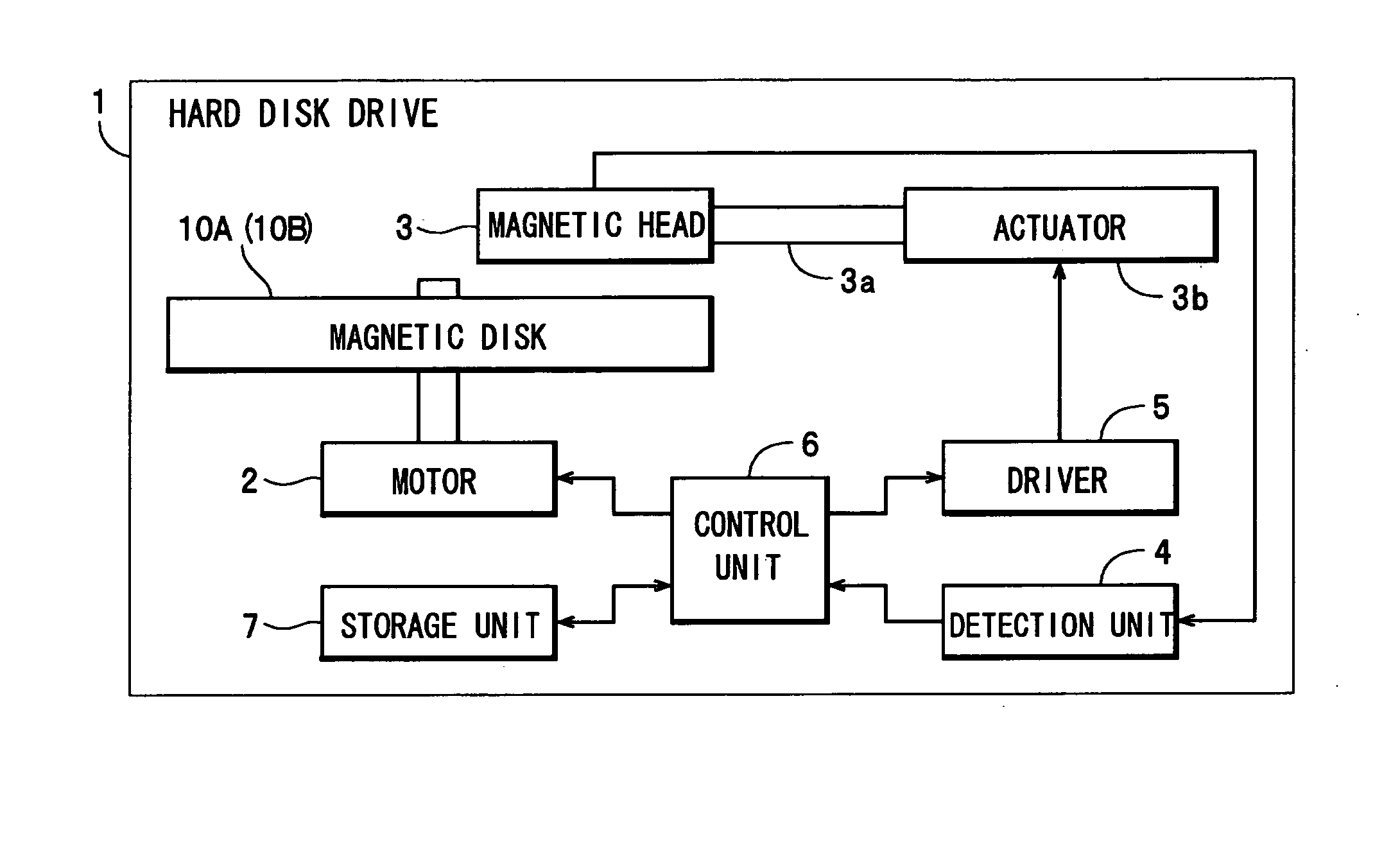
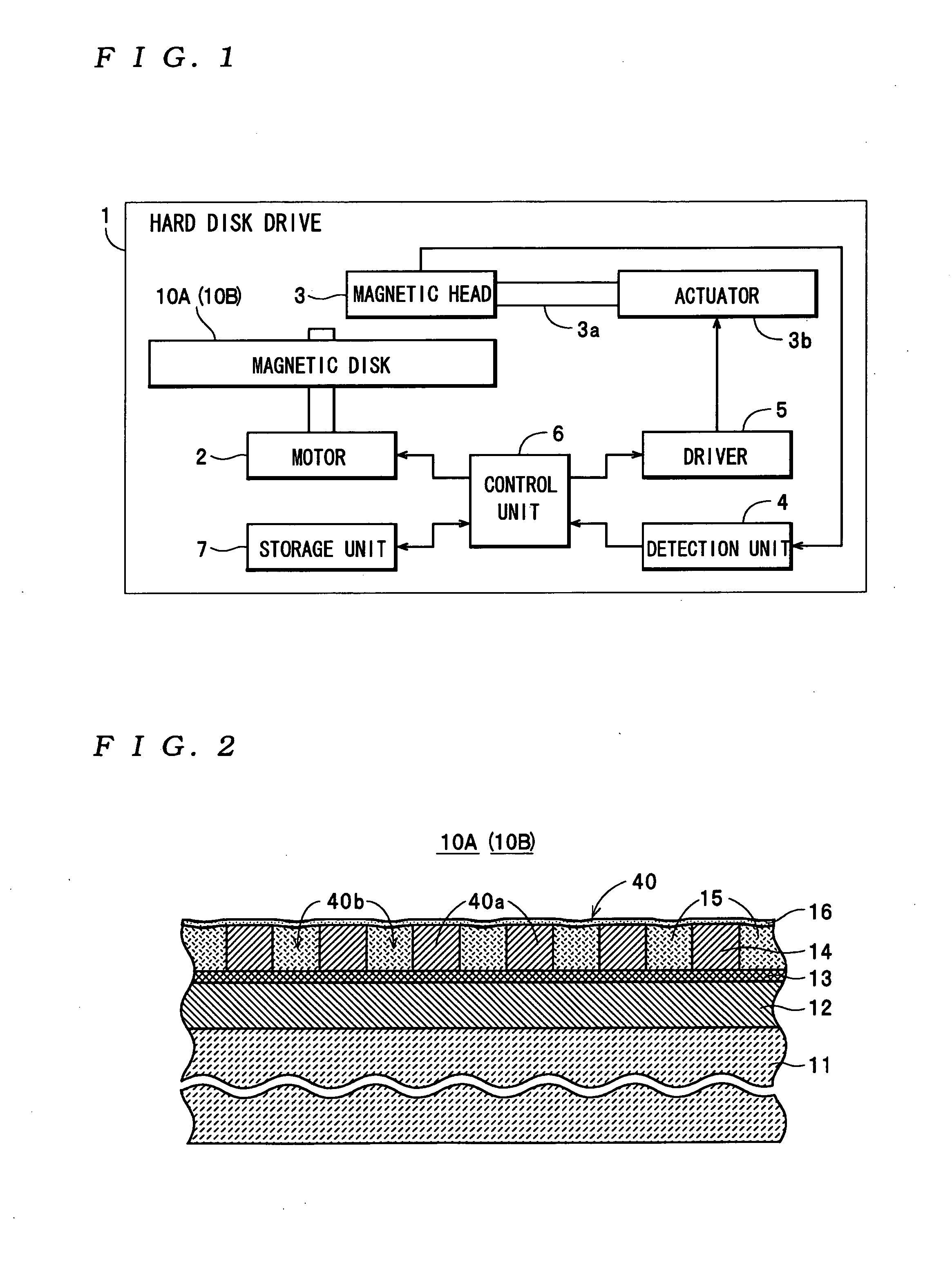
[0051] The hard disk drive 1 shown in FIG. 1 is one example of a recording / reproducing apparatus according to the present invention, includes a motor 2, a magnetic head 3, a detection unit 4, a driver 5, a control unit 6, a storage unit 7, and a magnetic disk 10A, and is capable of recording and reproducing various kinds of data. The motor 2 rotates the magnetic disk 10A at a fixed rotational speed, such as 4200 rpm, under the control of the control unit 6. The magnetic head 3 is attached to an actuator 3b via a swing arm 3a and is moved above the magnetic disk 10A during the recording and reproducing of recording data on the magnetic disk 10A by the actuator 3b. Also, the magnetic head 3 carries out reads of servo data from servo pattern regions Asa (see FIG. 4) of the magnetic disk 10A, m...


PUM


Abstract

On a magnetic recording medium, M sets of burst patterns are formed along a direction of rotation of a substrate in each burst pattern region, where M is a natural number of two or higher. Each burst pattern is formed so as to include two types of burst signal units that are positioned at different distances from a center of data track patterns and have an equal length along a radial direction of the substrate. The length along the radial direction is (2·M/N) times the track pitch, where N is a natural number of two or higher. In a predetermined range where both ends in the radial direction do not match a center in the radial direction of a burst pattern, (2·M) centers in the radial direction of the burst patterns are present at intervals of (1/N) times the track pitch in the radial direction, the two types of burst signal units are formed of non-recording regions and do not overlap each other in the direction of rotation, centers of the burst signal units in the radial direction are separated by (M/N) times the track pitch, and facing end parts in the radial direction of the burst signal units are separated via recording regions.

Description

BACKGROUND OF THE INVENTION [0001] 1. Field of the Invention [0002] The present invention relates to a magnetic recording medium on which burst patterns are formed by patterns that include recording regions and non-recording regions, a recording / reproducing apparatus equipped with the magnetic recording medium, and a stamper for manufacturing the magnetic recording medium. [0003] 2. Description of the Related Art [0004] As examples of this type of magnetic recording medium and recording / reproducing apparatus, Japanese Laid-Open Patent Publication No. H06-111502 discloses a magnetic disk apparatus equipped with a magnetic disk on which recording track patterns and servo patterns are formed by concave / convex patterns. On the magnetic disk provided in the magnetic disk apparatus, the recording track patterns and the servo patterns are formed by concave / convex patterns formed in a magnetic layer on a disk substrate. More specifically, as shown in FIG. 22, on a conventional magnetic disk...

Claims


Application Information

Patent Timeline
IPC IPC(8): G11B5/09G11B5/86G11B5/596
CPCB82Y10/00G11B5/59655G11B5/743G11B5/82G11B5/865
Inventor KAIZU, AKIMASASOENO, YOSHIKAZUMORIYA, MAKOTO
Owner TDK CORPARATION
Why Eureka
Try Eureka