Autofocus camera

a technology of autofocus and camera, applied in the field of cameras, can solve the problems of substantially limited movement of the lens, and achieve the effects of substantially enhancing the performance of the camera, preventing excessive movement of the stage, and reducing electromagnetic interference with the camera

Active Publication Date: 2006-09-14
DIGITALPTICS MEMS
View PDF22 Cites 79 Cited by
  • Summary
  • Abstract
  • Description
  • Claims
  • Application Information

AI Technical Summary

Benefits of technology

[0016] The cover can be formed of metal and can be configured so as to mitigate electromagnetic interference with the camera. Thus, performance of the camera can be substantially enhanced.
[0017] According to an embodiment of the present invention, a miniature camera can comprise an imaging sensor, an optics assembly having at least one movable optical element wherein movement of the optical element(s) effect focusing of the camera, a MEMs stage to which the movable optical element(s) are attached such that the stage controls motion of the movable optical element(s), and an actuator for moving the stage.
[0018] According to an embodiment of the present invention, a miniature camera can comprise an imaging sensor, a housing, and a MEMS stage disposed within the housing wherein the MEMS stage is configured so as to move substantially only in one degree of freedom. A snubber assembly can be configured to further limit movement of the MEMS stage substantially in five degrees of freedom, so as to protect the stage from excessive movement. A lens holder can be attached to one surface, e.g., the upper surface, of the stage. At least one focusing lens can be attached to the lens holder.
[0019] An actuator can be disposed within the housing. The actuator can comprise a coil attached to the housing and a magnet attached to the stage. The housing can align the coil with respect to the magnet and can also align the stage with respect to the imaging sensor. A bias spring can be configured to bias the stage into a predefined position with respect to the housing. The metal cover can be configured to substantially enclose the actuator and the imaging sensor. The actuator can effect movement of the lens so as to provide desired focusing of an image upon the imaging sensor.

Problems solved by technology

Thus, for example, a lens can be attached to the movable portion of the MEMS stage and movement of the lens can be substantially limited to movement in one degree of freedom.

Method used


Image

  • Autofocus camera
  • Autofocus camera
  • Autofocus camera

Examples


Embodiment Construction

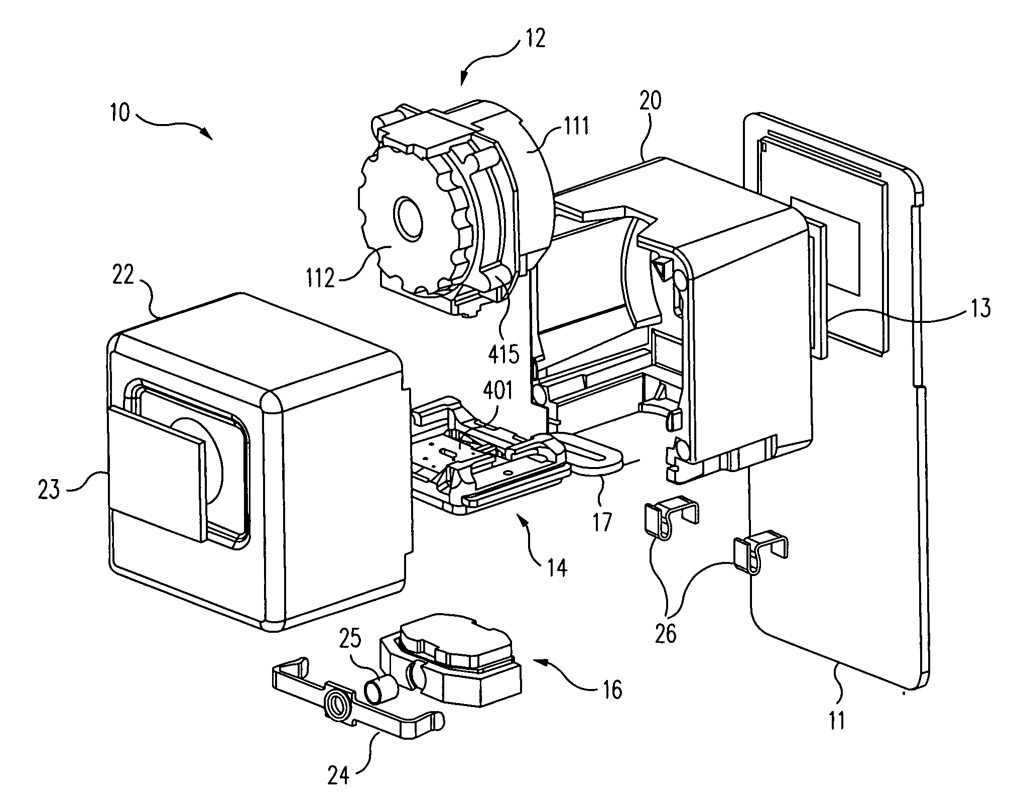
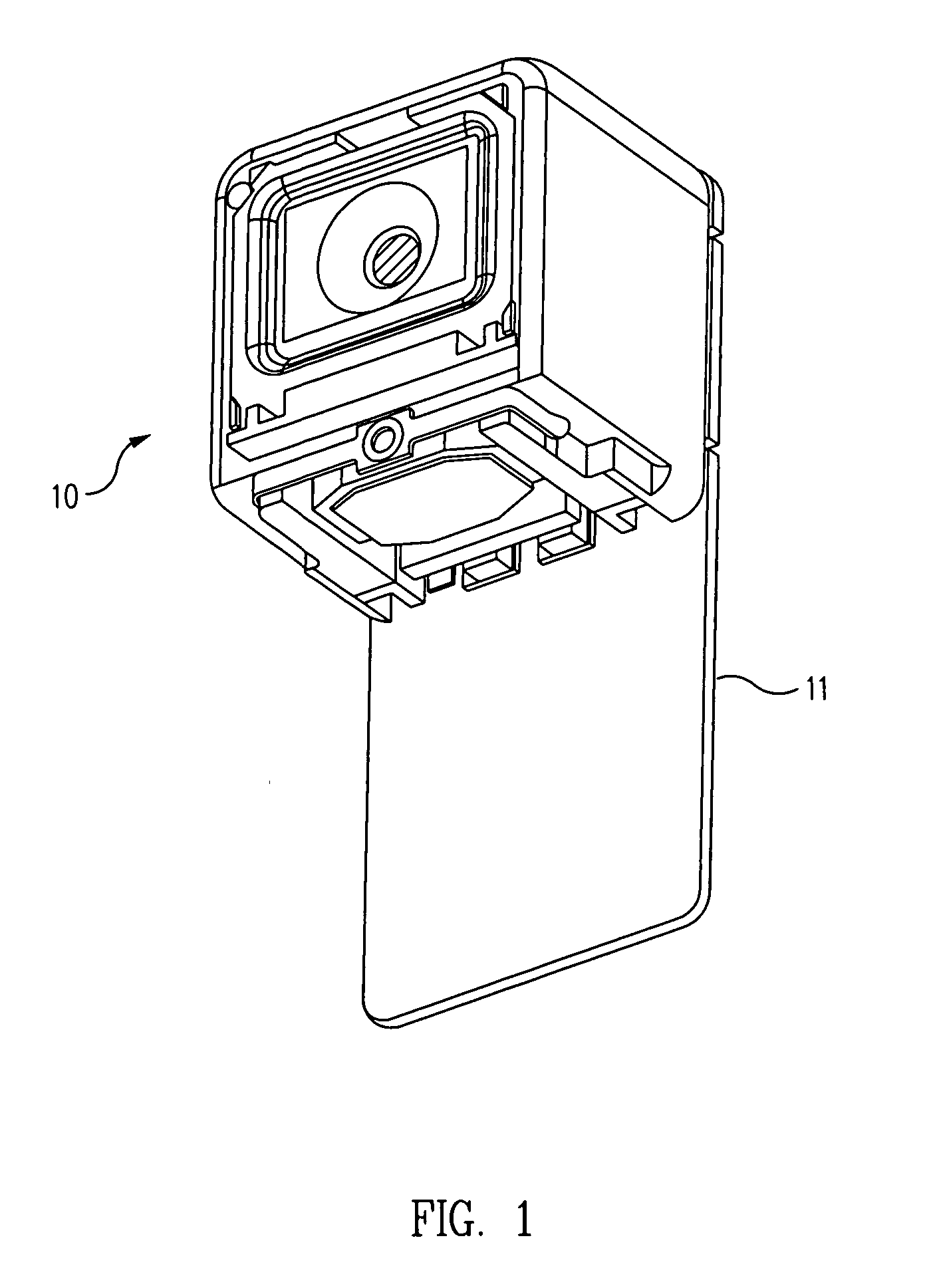
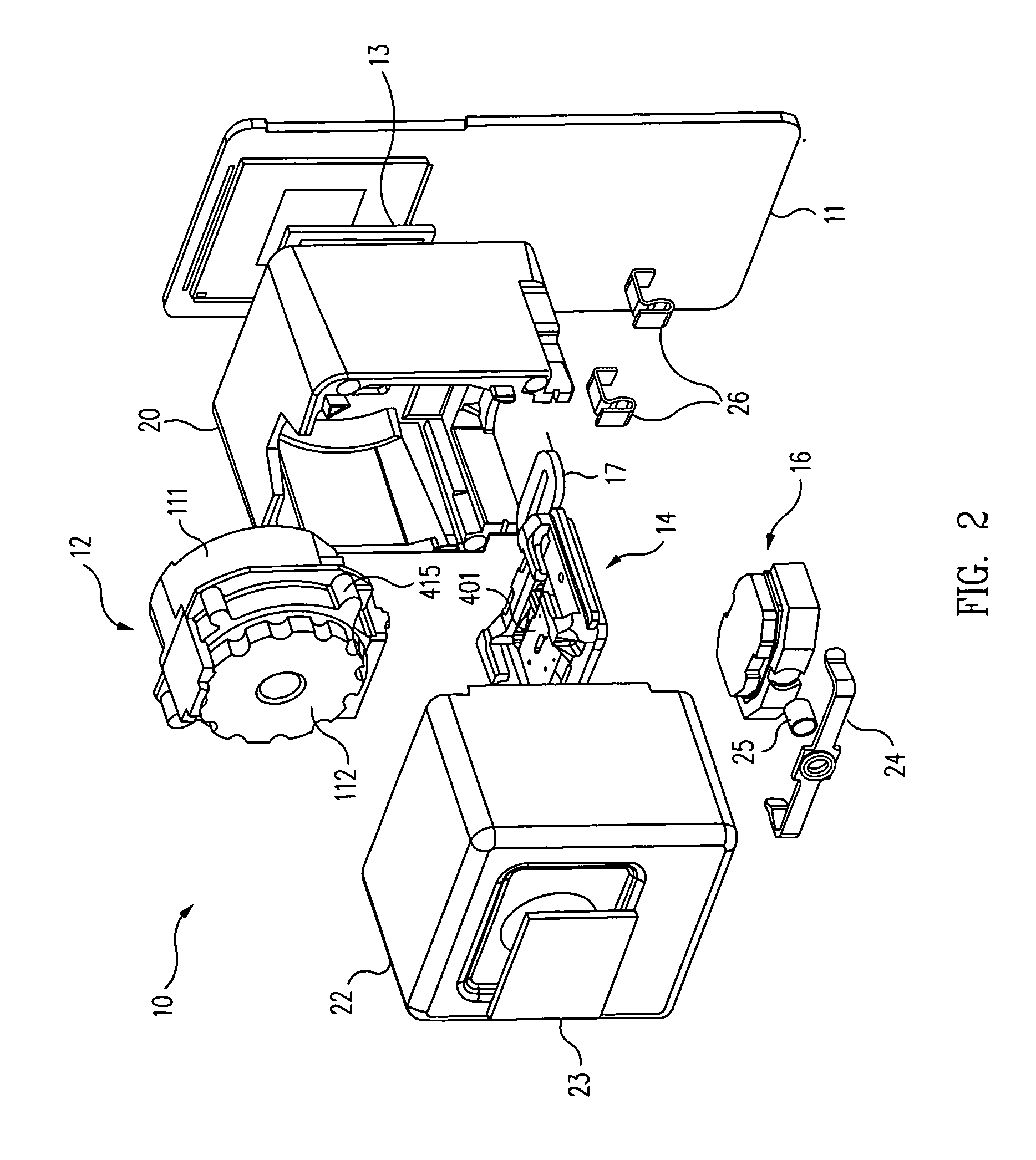
[0042] When an optical system is reduced in size, the precision required for the placement of optical elements has to be improved in proportion to the reduction in size. In other words, optical systems can scale in size linearly. For cameras in cellular telephones, the reduction in the size of the imaging system can be dramatic. It is thus a challenge to be able to position and move the optical elements with respect to each other with the required precision.

[0043] To be able to accomplish autofocus in a cellular telephone camera, it is common to move a lens or group of lenses. The position and motion of these lenses has to be very precise. Achieving such precision using contemporary technologies is difficult.

[0044] One or more embodiments of the present invention provide enhanced precision in the motion of very small camera components by using a micro electromechanical systems (MEMS) stage. This MEMS stage provides for very precise control in the motion of a lens and accomplishes ...


PUM

PropertyMeasurementUnit
degree of freedomaaaaaaaaaa

Abstract

A method and system for facilitating focusing of a miniature camera are disclosed. One or more lenses can be attached to a MEMS stage. The MEMS stage can be moved by a Lorentz actuator. The MEMS stage can be configured to limit movement of the lens(es) to a single degree of freedom to inhibit misalignment thereof with respect to an imaging sensor. The stage can be biased to a predefined position thereof, e.g., for focus at infinity. A metal cover can inhibit electromagnetic interference and can limit movement of the lens(es).

Description

PRIORITY CLAIM [0001] This patent application claims the benefit of the priority date of U.S. provisional patent application Ser. No. 60 / 657,261, filed on Feb. 28, 2005 and entitled AUTOFOCUS CAMERA (docket no. M-15826-V1US) pursuant to 35 USC 119. The entire contents of this provisional patent application are hereby expressly incorporated by reference. [0002] This patent application is a continuation-in-part (CIP) of U.S. patent application Ser. No. 11 / 268,849, filed on Nov. 8, 2005 and entitled CAMERA SNUBBER ASSEMBLY (docket no. M-15915 US) and U.S. patent application Ser. No. 11 / 269,304, filed on Nov. 8, 2005 and entitled AXIAL SNUBBERS FOR CAMERA (docket no. M-15916 US). The entire contents of both of these patent applications are hereby expressly incorporated by reference.TECHNICAL FIELD [0003] The present invention relates generally to cameras. The present invention relates more particularly to a miniature autofocus camera that is suitable for use in personal electronic devic...

Claims


Application Information

Patent Timeline
Patent Type & Authority Applications(United States)
IPC IPC(8): G03B17/00B29C48/76
CPCG02B7/08Y10T29/4902G02B13/001G03B17/02G03B3/10H04N23/51H04N23/54H04N23/55G02B7/09G03B13/36
Inventor GUTIERREZ, ROMAN C.CALVET, ROBERT J.HARRINGTON, DARRELLWANG, GUIQINJAYARAJ, KUMARASWAMY
Owner DIGITALPTICS MEMS
Why Eureka
Try Eureka