
Controlled evacuation ostomy device with external seal

a technology of ostomy and seal, which is applied in the field of ostomy devices, can solve the problems of affecting the treatment effect, and affecting the treatment effect, and achieves the effect of preventing the release of stool and good barrier properties

Inactive Publication Date: 2006-09-14
CONVATEC TECH INC
View PDF30 Cites 60 Cited by
  • Summary
  • Abstract
  • Description
  • Claims
  • Application Information

AI Technical Summary

Benefits of technology

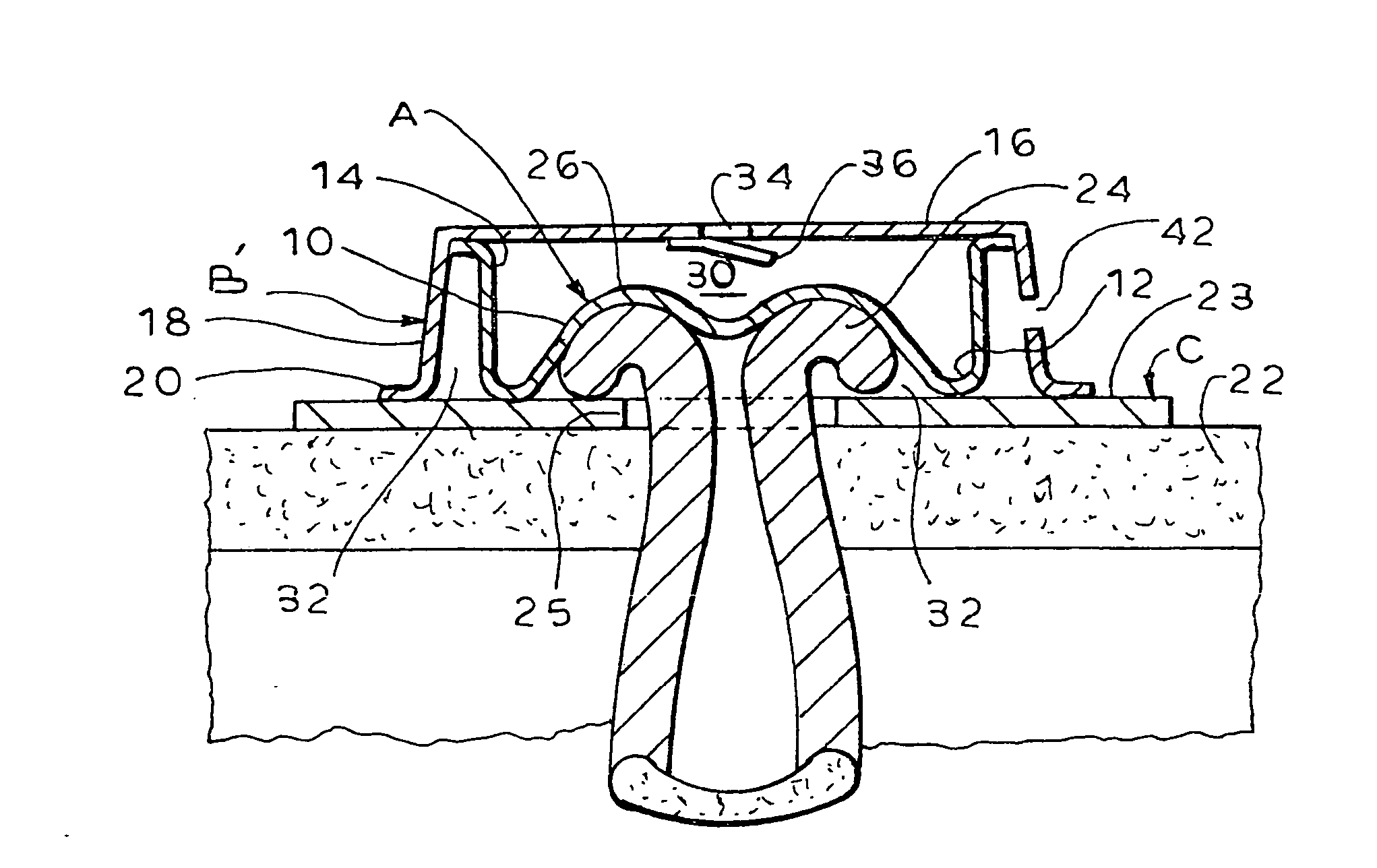
[0014] The seal, which forms the subject of the invention, is designed to be mounted externally and to exert a low pressures (preferably between 10 mm Hg and 30 mm Hg) across the entire face of the stoma. The seal itself is formed of a thin and flexible membrane. The membrane is preferably made of a material with good barrier properties. One possible candidate material is the film used in the manufacture of ostomy pouches. Under a minimal amount of external pressure, the membrance drapes itself across and around the stoma, covering most surface irregularities. Based on preliminary laboratory test results, the device can prevent release of stool from the bowel with internal bowel pressure of 50 mm Hg and above.
[0015] Such a seal would adapt itself to a variety of stoma sizes and shapes. It would also be, by design, a slightly“imperfect” seal, so that it would block the release of solid or semi-solid matter but would allow gas to escape. The ability of the seal to permit gas to escape is important to the management of waste in the bowel, since at any given time more than two-thirds of the volume in the bowel is gas. Releasing gas in a controlled way minimizes discomfort and maximizes the time between evacuations.

Problems solved by technology

These ostomy devices collect waste as it is discharged but include no means for controlling when discharge takes place.
However, having discharge take place into the collection pouch in certain situations may cause embarrassment to the wearer because of the noise or smell or because of the increase in the size of the pouch.
High local pressure can damage the stoma.
Thus, any acceptable evacuation control device must seal the stoma exerting harmful pressure on the stoma or surrounding tissue.

Method used


Image

  • Controlled evacuation ostomy device with external seal
  • Controlled evacuation ostomy device with external seal
  • Controlled evacuation ostomy device with external seal

Examples


Embodiment Construction

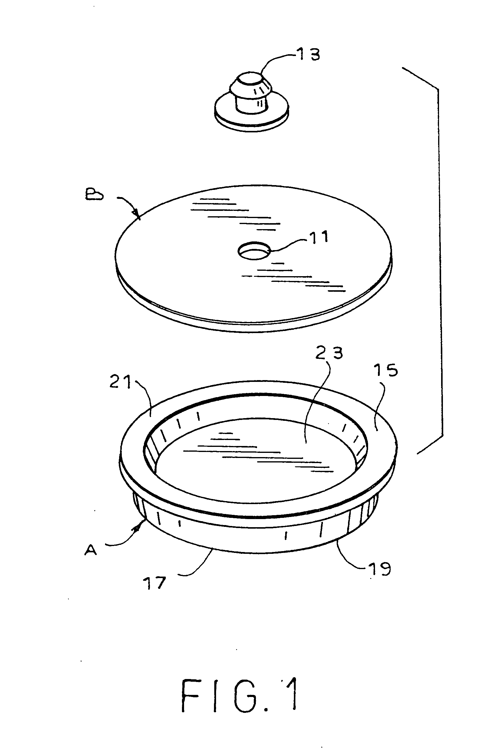
[0054] As illustrated in FIG. 1, the present invention in its simplest form comprises a thin, flexible membrane, generally designated A and a disc-like cover member, generally designated B. Member B includes a port 11. A plug 13 is provided to seal port 11.

[0055] Membrane A has a cup shape with a closed bottom and an outwardly extending top flange 15. A layer of adhesive 17 is situated on the rim 19 of the bottom of the membrane to seal the membrane to the tissue surrounding the stoma.

[0056] A second layer 21 of adhesive is placed on flange 15 so as to seal member B to flange 15. Between membrane A and member B is a defined internal chamber 23.

[0057] Chamber 23 is pressurized by forcing air or other fluid through port 11. This can be accomplished by using an external pump device, not shown in this figure. Once the chamber is pressurized to the desired degree, the port is sealed by plug 13. The pressure within the chamber causes membrane A to press against the stoma to seal the st...


PUM


Abstract

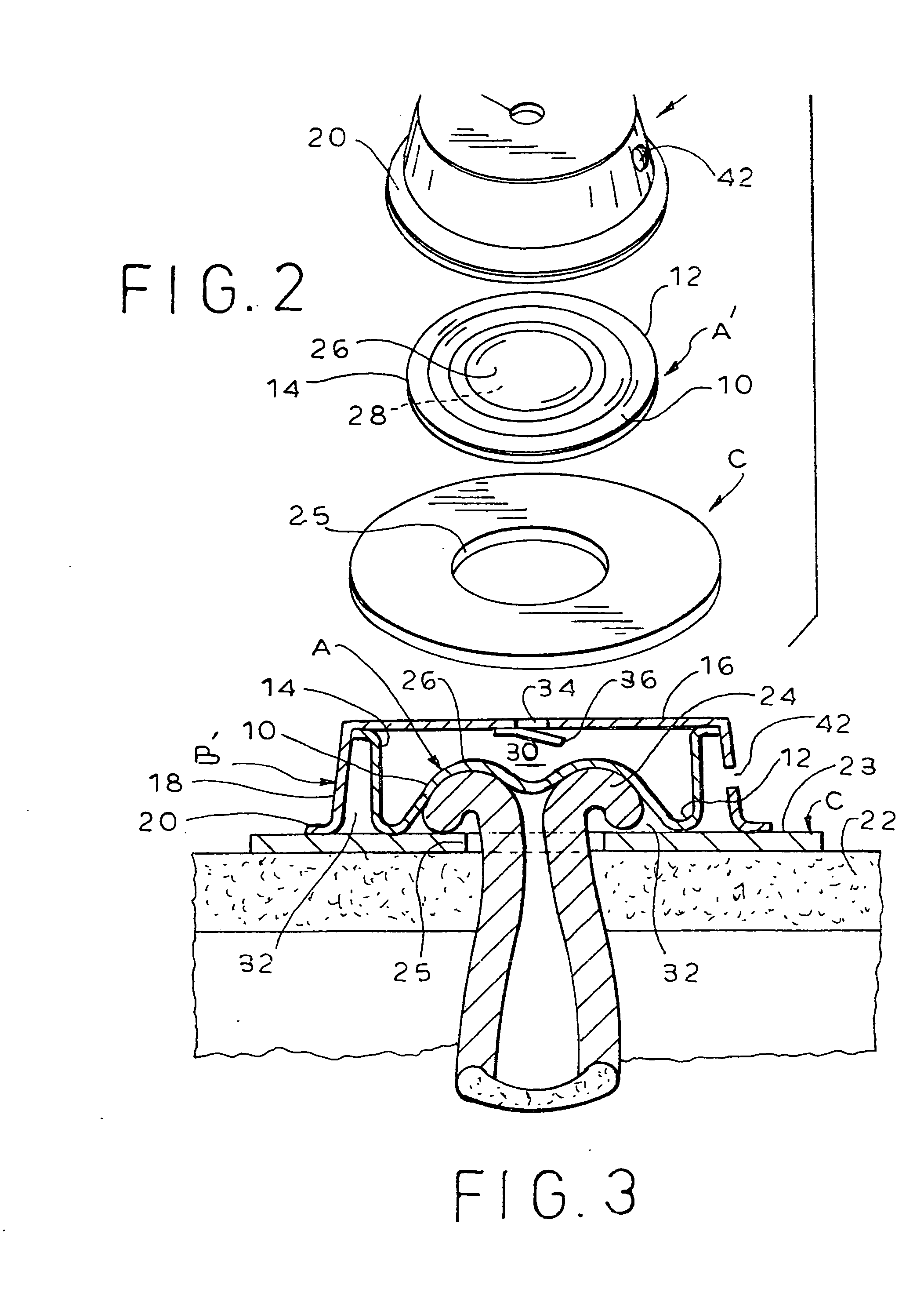
A flexible membrane is situated within a rigid or semi-rigid cap. The edge of the cap wall is adhesively fixed to the tissue surrounding the stoma. The interior of the cap is pressurized to press the membrane to seal the stoma against the discharge of solid and semi-solid waste. Gas escapes through a vent with a filter element. The cap can be pressurized by an external pump or an integral pump member situated on top of the cap. A relief valve prevents over pressurization. A collection pouch can be provided as part of a device. The device can be removably mounted on a standard two-piece faceplate.

Description

CROSS-REFERENCE TO RELATED APPLICATIONS [0001] This application is a divisional of application Ser. No. 10 / 881,055 filed Mar. 26, 2004 which is a continuation of application Ser. No. 10 / 107,998 filed Mar. 27, 2002, now U.S. Pat. No. 6,723,079.STATEMENT REGARDING FEDERALLY SPONSORED RESEACH OR DEVELOPMENT [0002] Not Applicable INCORPORATION-BY-REFERENCE OF MATERIAL SUBMITTED ON A COMPACT DISC [0003] Not Applicable BACKGROUND OF THE INVENTION [0004] (1) Field of the Invention [0005] The present invention relates to ostomy devices of the type adapted to be adhesively affixed to the skin surrounding the stoma and more particularly to such a device which includes external means for controlling evacuation by sealing the stoma while exerting only a minimum amount of sealing pressure. [0006] Certain surgical procedures known as colostomy, ileostomy and urostomy result in an opening in the abdominal wall, called a stoma, which permits waste discharge from the interior of a body cavity. Since...

Claims


Application Information

Patent Timeline
Patent Type & Authority Applications(United States)
IPC IPC(8): A61F5/44A61F5/445A61F5/448
CPCA61F5/445A61F5/448
Inventor CLINE, JOHN B.
Owner CONVATEC TECH INC
Learn More