Drum washing machine

Active Publication Date: 2006-09-21
TOSHIBA LIFESTYLE PROD & SERVICES CORP
View PDF11 Cites 44 Cited by
  • Summary
  • Abstract
  • Description
  • Claims
  • Application Information

AI Technical Summary

Benefits of technology

[0011] As described above, laundry needs to be balanced in the drum in order that the laundry weight may be estimated with high accuracy. Since the q-axis current value in the vector control direct

Problems solved by technology

These two critical speeds do n

Method used


Image

  • Drum washing machine
  • Drum washing machine
  • Drum washing machine

Examples


Example

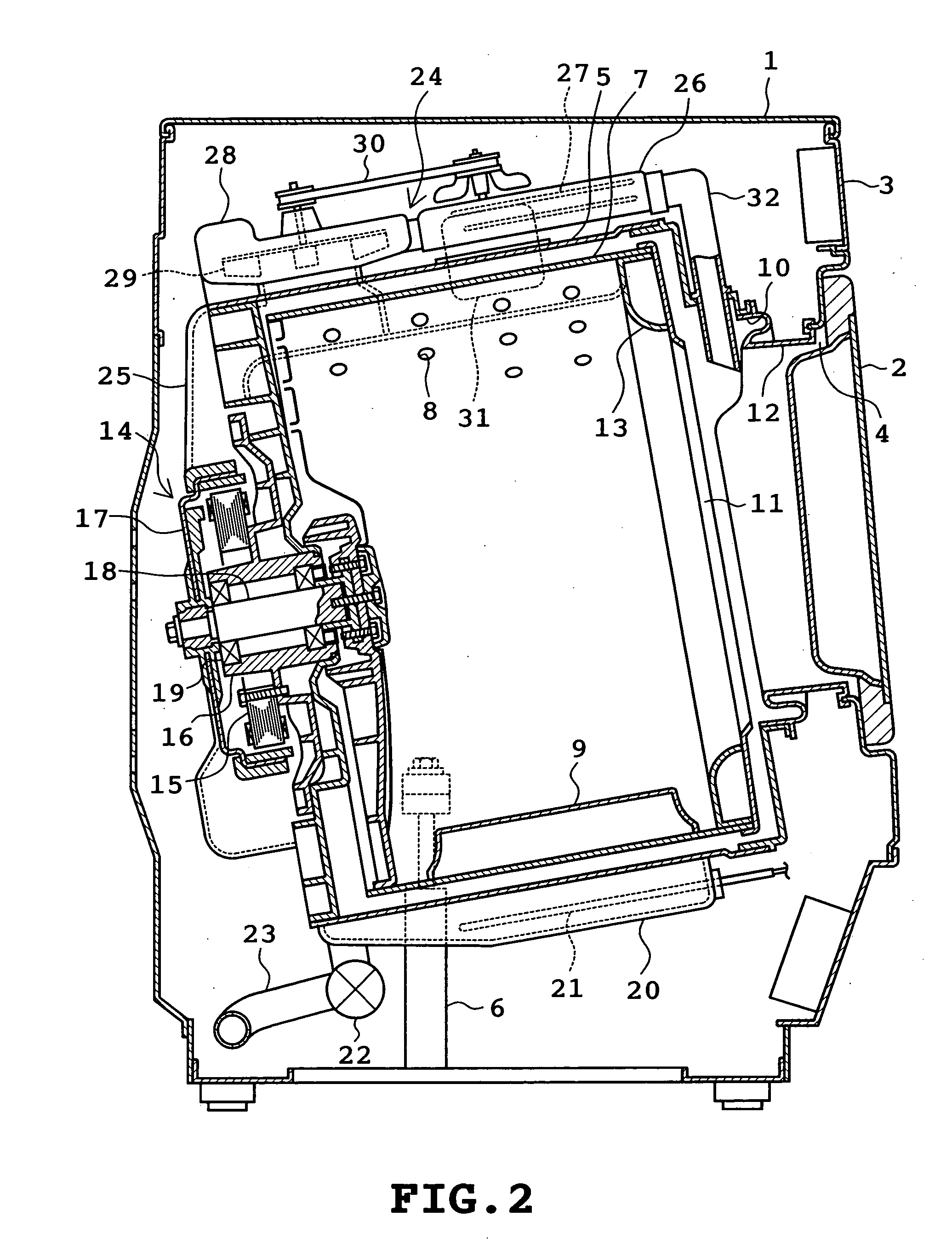
[0027] A first embodiment of the present invention will be described with reference to FIGS. 1 to 9. Referring to FIG. 2, an overall construction of the drum washing machine is shown. The drum washing machine comprises an outer cabinet 1 serving as an outer shell of the drum washing machine. The outer cabinet 1 is provided with a door 2 mounted on the central front thereof and an operation panel 3 mounted on the upper front thereof. The operation panel 3 includes a number of switches and display sections none of which are shown. The door 2 closes and opens an access opening 4 formed in the central front of the outer cabinet 1. Laundry is put into and taken out of a drum 7 through the access opening 4.

[0028] A cylindrical water tub 5 is disposed in the outer cabinet 1. The water tub 5 has an axis extending substantially horizontally in the back-and-forth direction so that a rear portion thereof is inclined downward. The water tub 5 is elastically supported by elastically supporting ...

Example

Second Embodiment

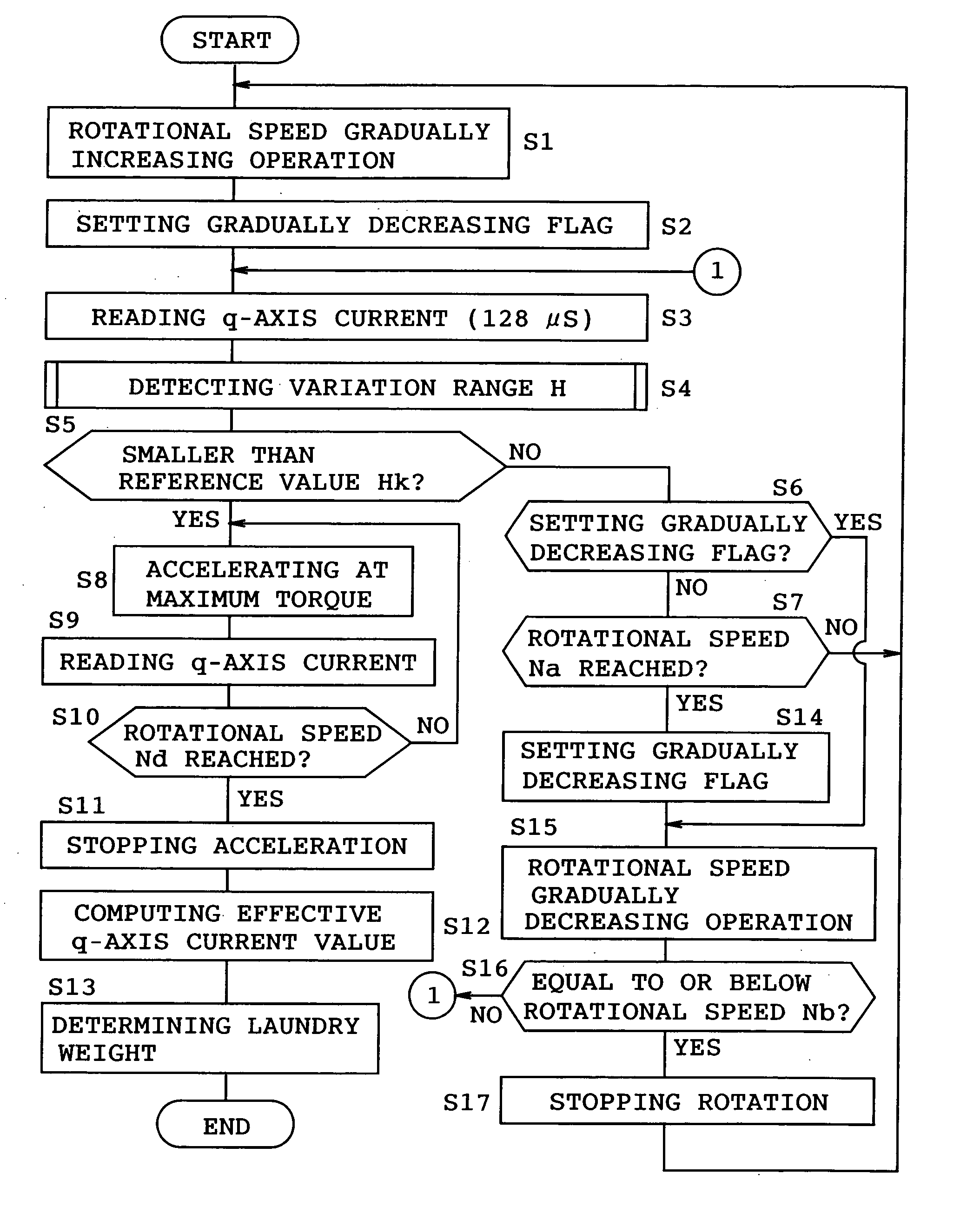
[0055]FIGS. 8 and 9 illustrate a second embodiment of the invention. Identical or similar parts in the second embodiment are labeled by the same reference symbols as those in the first embodiment. Only the difference of the second embodiment from the first embodiment will be described in the following. The arrangement of the second embodiment is basically the same as that of the first embodiment, but the software contents for the control microcomputer in the second embodiment differ from those in the first embodiment.

[0056] In the second embodiment, the rotational speed of the drum 7 is once increased to the upper reference speed Na(step S21) and thereafter, the rotational speed is gradually decreased toward the lower reference speed Nb(maximum period Tk) (step S22). Subsequently, steps S3 to S5 and S8 to S13 are executed in the same manner as in the first embodiment. Further, when determining in the negative (NO) at step S5, the control microcomputer 54 carries o...

Example

Third Embodiment

[0060] FIGS. 10 to 15 illustrate a third embodiment of the invention. In the third embodiment, the d-axis current in the vector control is also used for the purpose of estimating the laundry weight.

[0061] Firstly, the principles of the estimation will be described with reference to FIGS. 14 and 15. FIG. 14 is a graph on which are plotted determination values measured when the temperature of the motor 14 (mainly the winding temperature) is changed and the drum 17 is rotated under no load condition, the condition of a 2.2 kg artificial load, and the condition of a 5.3 kg artificial load. Regarding each condition, measured points are divided into two groups. The lower temperature side group indicates the case where the room temperature is at 14° C., whereas the higher temperature side group indicates the case where the room temperature is at 26° C. FIG. 14 shows that a determination value tends to become larger under the same load condition as the temperature of the m...


PUM


Abstract

A drum washing machine includes a drum (7) accommodating laundry and having a substantially horizontal axis of rotation, an electric motor (14) rotating the drum (7), current detecting means (47) for detecting an electric current flowing through the motor (14), torque control means (53) for vector-controlling the motor (14) on the basis of the current detected by the current detecting means (47) so that torque developed by the motor (14) becomes optimum at least in each of a wash operation and a dehydration operation, and laundry weight estimating means (54, 61) or accelerating the motor (14) with a maximum output torque developed when determining that a rotational speed of the motor (14) is between a first rotational speed at which the laundry is assumed to start falling from an uppermost part of an inner periphery of the drum (7) when the rotational speed of the motor (14) is reduced from a high speed side and a second rotational speed at which the laundry in the drum is assumed to start sticking to an uppermost part of the inner periphery of the drum (7), thereby estimating a laundry weight according to a q-axis current value in the vector control during an accelerating period.

Description

TECHNICAL FIELD [0001] The present invention relates to a drum washing machine in which a vector control is carried out for the control of output torque of an electric motor rotating a drum. BACKGROUND ART [0002] In conventional drum washing machines, a rotational speed of a drum is increased to a predetermined first value in determination of the weight of laundry in a drum and is further increased from the predetermined value to another second higher speed. The laundry weight is determined on the basis of the length of time length required for the rotational speed to be increased from the first value to the second value. However, when the rotational speed of the drum is in a higher range, windage loss occurs, or friction produced between an access cover of the drum in a stationary state and cloth is increased. As a result, it is difficult to obtain the detection results in proportional to the difference in laundry weight. Thus, the accuracy in the detection is reduced. [0003] Furth...

Claims


Application Information

Patent Timeline
IPC IPC(8): D06F33/00D06F33/02D06F25/00D06F39/00
CPCD06F2202/12D06F39/003D06F34/18D06F2103/04D06F2103/46D06F2103/52D06F2105/48
Inventor OKAZAKI, YOJIHOSOITO, TSUYOSHI
Owner TOSHIBA LIFESTYLE PROD & SERVICES CORP
Why Eureka
Try Eureka