Method and a device for slowing down and disintegrating a plug of liquid plunging forward in a duct

a technology of a duct and a plug, which is applied in the direction of rigid pipes, pipe elements, light and heating apparatus, etc., can solve the problems of a large force on the conduit system, a large kinetic energy obtained by the forward plunging plug of water, and a very harmful impact on the secondary conduit system of the plug

Inactive Publication Date: 2006-09-21
VATTENFALL
View PDF9 Cites 22 Cited by
  • Summary
  • Abstract
  • Description
  • Claims
  • Application Information

AI Technical Summary

Problems solved by technology

This means that the swept-along and forward plunging plug of water obtains an extremely large kinetic energy, meaning that it may exert a very large force on the conduit system in connection with said plug of water changing the direction of flow or slowing down, for instance in bends or the like.
In other words, such plugs of water may have a very harmful impact on the secondary conduit system.

Method used


Image

  • Method and a device for slowing down and disintegrating a plug of liquid plunging forward in a duct
  • Method and a device for slowing down and disintegrating a plug of liquid plunging forward in a duct
  • Method and a device for slowing down and disintegrating a plug of liquid plunging forward in a duct

Examples


Embodiment Construction

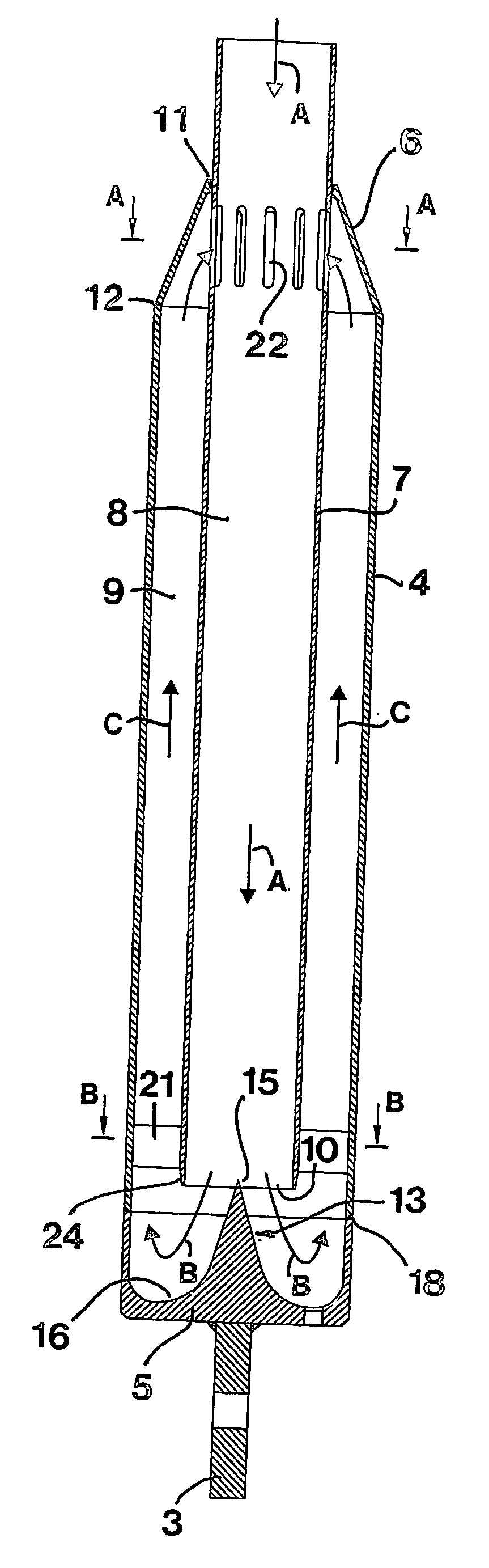
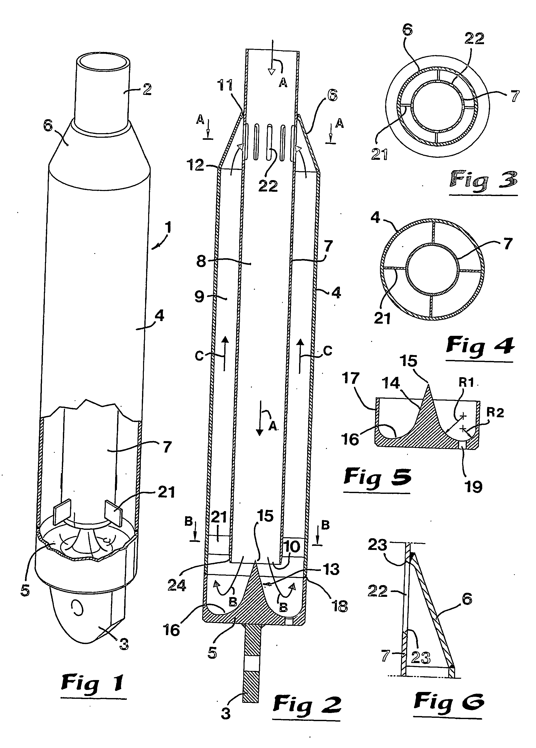
[0018] In FIG. 1, 1 generally designates a long narrow container that at one end thereof—in this case the upper end—has an inlet 2 for receiving a plug of water, and at the opposite end thereof has a sturdy fastening ear 3, by means of which the container can be held in place in a mounted state. In the example, the container 1 is composed of a cylindrical tube 4, an end wall or bottom 5 distanced from the inlet 2, as well as a closing wall 6, which extends between the tube 4 and the inlet 2. In practice, the container is suitably—though not necessarily—mounted in the vertical state shown, meaning that the end wall 5 forms a bottom. The container has a considerably larger volume than the plug of water of at most approx. 20 l that is to be received in the same. In a concrete embodiment example, hence the tube 4 has a length of approx. 1.5 m and a diameter of approx. 0.3 m, i.e., a volume of approx. 0.1 cubic metre.

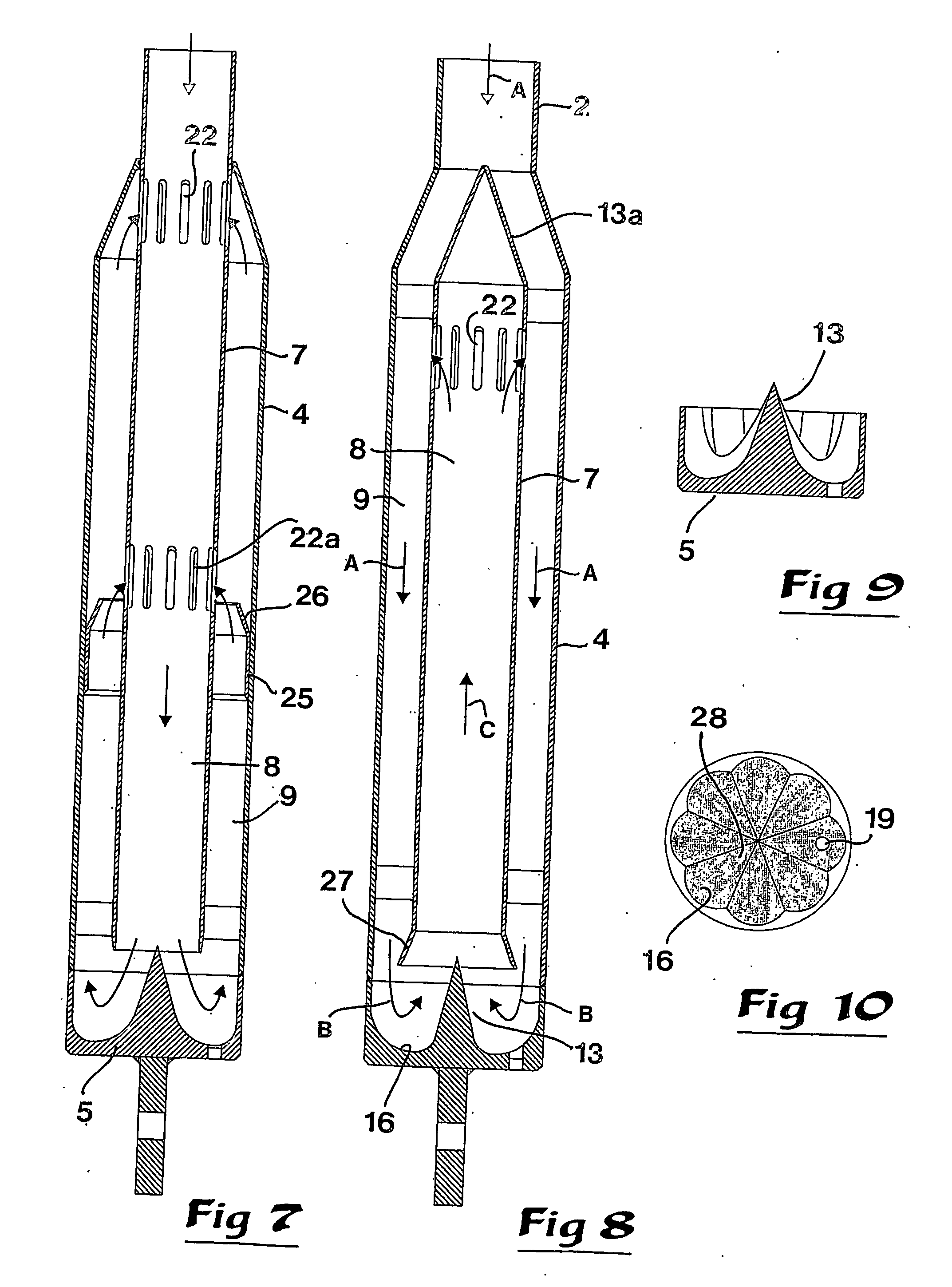
[0019] Inside the tube 4, an inner tube 7 is arranged having a smaller...


PUM


Abstract

A device for slowing down and disintegrating a plug of liquid plunging forward in a duct includes a container having a bottom and an opposite inlet, which is connectable to the duct and through which the plug of liquid can be directed into a central, axial trajectory in the container. Inside the container is an inner tube, open towards the bottom, which separates an inner hollow space from an outer, cross-section-wise ring-shaped hollow space, a distributor body being arranged in the trajectory of the entering plug of liquid for splitting and disintegrating the plug of liquid as well as throwing out the disintegrated constituent parts of liquid in the direction outwards from the center. The bottom includes a concavely curved guide surface for diverting the liquid from one of the hollow spaces to the other to reverse the direction of motion of the liquid. A corresponding method is also provided.

Description

BACKGROUND OF THE INVENTION [0001] In nuclear power plants that make use of pressurized water reactors, water is brought under pressure to circulate between the reactor and a boiler. In this conduit system, a pressure-retention tank is included that works as an expansion vessel and has the purpose of absorbing possible variations in pressure in the conduit system. To said pressure-retention tank, a plurality of relief and blow-off valves are connected via particular conduits, which valves have the purpose of becoming opened in order to discharge steam from the pressure-retention tank in case the pressure in the same would unintentionally increase above predetermined maximum permissible values. Immediately up-stream each such valve, a water seal is present that has the purpose of preventing hydrogen gas from reaching and passing the valve (together with the oxygen of the air, hydrogen gas may form explosive detonating gas). The water seal consists of approx. 5-20 L of water that rest...

Claims


Application Information

Patent Timeline
Patent Type & Authority Applications(United States)
IPC IPC(8): F24H9/12F16L55/045
CPCF16L55/045Y02E30/00G21D1/00
Inventor HENRIKSSON, MATSBYSTROM, ANDERS
Owner VATTENFALL
Why Eureka
Try Eureka