Apparatus and method for connecting coated wires

Inactive Publication Date: 2006-09-21
WELTER CURTIS L
View PDF12 Cites 28 Cited by
  • Summary
  • Abstract
  • Description
  • Claims
  • Application Information

AI Technical Summary

Benefits of technology

[0027] It is therefore an object of this invention to incorporate both ultrasonic and resistive welding techniques to produce stronger weldments between thin covered wire and conductive objects such as wire terminals and other covered wire.
[0028] Still another object of this invention is the utilization of ultrasonic-resistance welding technique

Problems solved by technology

However, in applying the ultrasonic welding technique to small wires and leads, damage can occur to the wire itself during the process which will then lead to premature wire failure or increased resistance as a result of the loss of some of the inner core strands being separated.
However, the wire covering has sufficient resistivity to render this process alone to be inadequate in and of its own to effects such welds commercially, requiring removal or stripping away of the portion of covering over the wire conductor before the resistance weld to the conductive terminal can be made.
A number of prior art patents as listed below disclose the independent processes of ultrasonic welding, heat welding and resistive welding of covered wire to a conductive object such as a wire terminal, but none appear to disclose a combination of ultrasonic equipment to first displace or remove the wire covering and

Method used


Image

  • Apparatus and method for connecting coated wires
  • Apparatus and method for connecting coated wires
  • Apparatus and method for connecting coated wires

Examples


Embodiment Construction

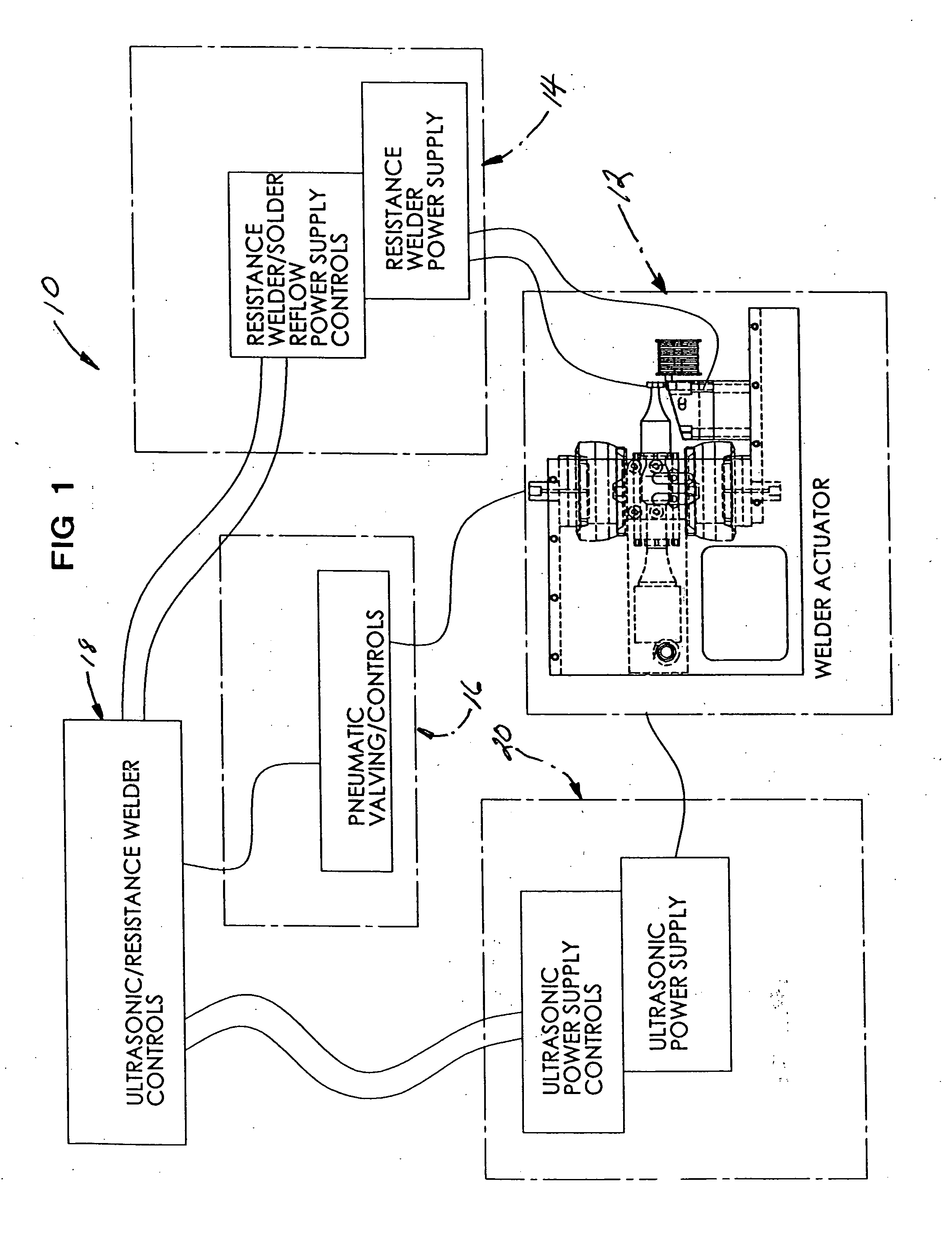
[0037] Referring now to the drawings, the apparatus of the invention is there shown generally at numeral 10 and includes an improved, ultrasonic welder 12, a power supply for a resistance welding process 14, pneumatic valving / control 16 which actuates the hydraulic or pneumatic actuators 44 / 46 or 44′ / 46′ of the ultrasonic welder 12 and a power supply 20 for the ultrasonic welder 12. One new aspect of the invention relates to the ultrasonic resistance welder controls 18 which regulates the sequential utilization of ultrasonic wire cleaning and resistive welding to accomplish a stronger weldment between small coated wire or objects and conductive objects such as wire terminals and other metal objects.

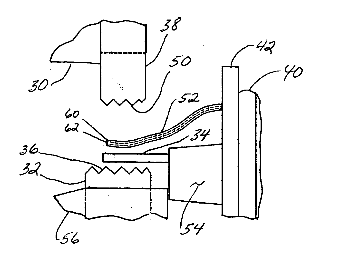
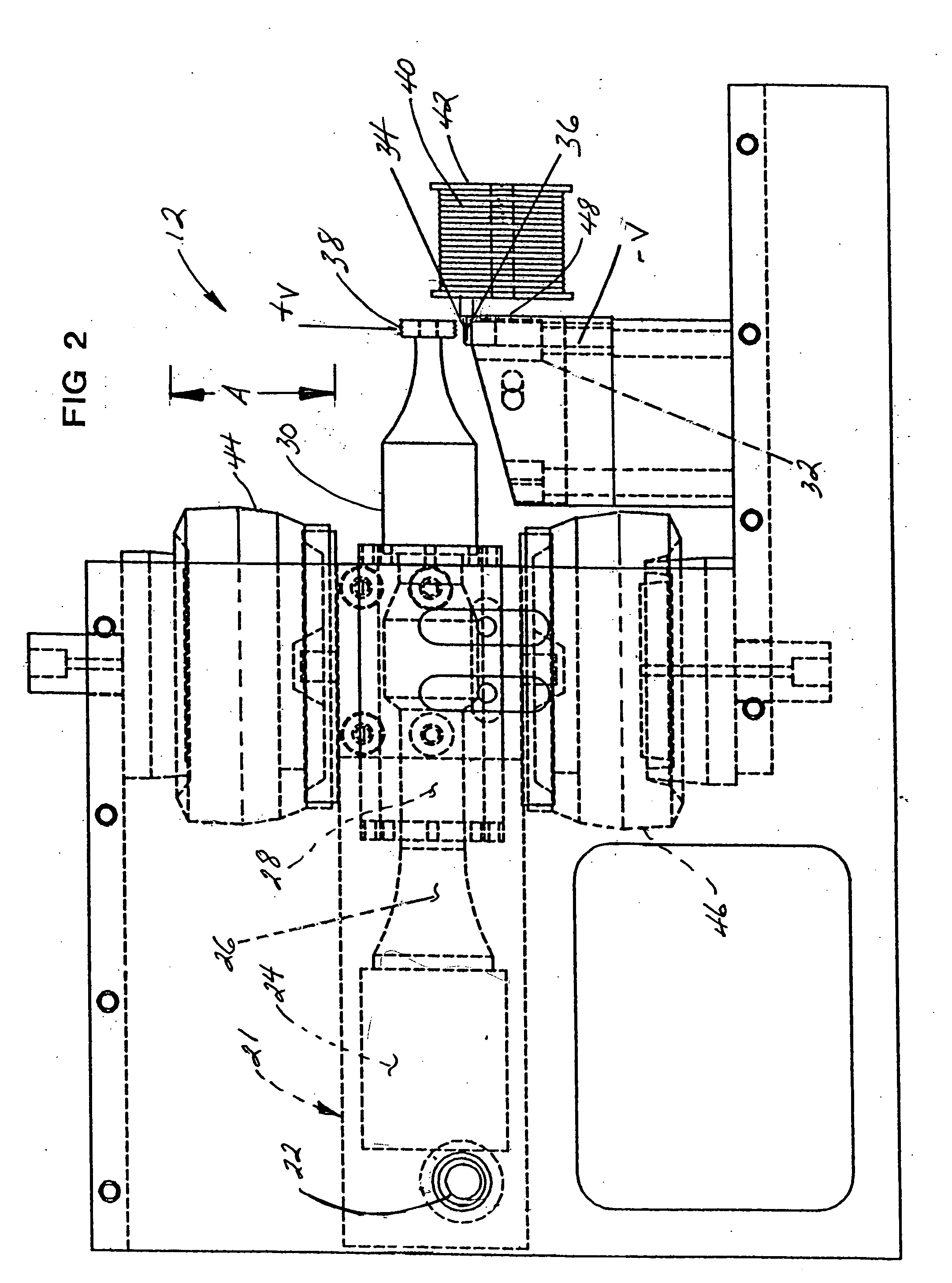
[0038] Referring to FIGS. 2 and 3, alternate embodiments of the improved ultrasonic welder are there depicted generally at numeral 12 and 12′. In FIG. 2, the ultrasonic welder 12 generally includes a carriage 21 pivotally movable about bearing 22 and including an ultrasonic converter tra...


PUM

PropertyMeasurementUnit
Poweraaaaaaaaaa
Electrical resistanceaaaaaaaaaa
Energyaaaaaaaaaa

Abstract

An apparatus and method of connecting a covered wire to a wire terminal which incorporates ultrasonic and resistance welding in sequence. The method includes (a) positioning the wire terminal against an anvil; (b) positioning the covered wire against the terminal; (c) positioning a tip of an ultrasonic welder in clamped engagement with the wire terminal and the covered wire together against the anvil; (d) ultrasonically vibrating the tip for a time sufficient for the covering against the terminal to be displaced and electrical contact established between the tip and the anvil through the wire and the terminal; and (e) applying sufficient electric current between the tip and the anvil to resistance weld the wire and the terminal together.

Description

CROSS-REFERENCE TO RELATED APPLICATIONS [0001] Not applicable STATEMENT REGARDING FEDERALLY SPONSORED RESEARCH OR DEVELOPMENT [0002] Not applicable INCORPORATION-BY-REFERENCE OF MATERIAL SUBMITTED ON A COMPACT DISC [0003] Not applicable BACKGROUND OF THE INVENTION [0004] 1. Field of the Invention [0005] This invention relates generally to apparatus and methods for connecting a coated wire with another metallic object such as another coated wire or wire terminal, and more particularly to the utilization of ultrasonic resistance welding in connecting a covered wire with a conductive wire terminal and the like. [0006] 2. Description of Related Art [0007] In production processes of attaching small covered or coated or jacketed wire having an inner conductive solid or stranded core or center to another object such as a similar covered wire, a wire terminal or other conductive object, the technique of ultrasonic welding is frequently utilized. In this process, pressure is applied against ...

Claims


Application Information

Patent Timeline
IPC IPC(8): B23K20/10B23K1/06
CPCB23K11/002B23K20/10B23K28/02B23K2201/38B23K2101/38
Inventor WELTER, CURTIS L.
Owner WELTER CURTIS L
Why Eureka
Try Eureka