Fluid mixing device for tub and bath fluid mixing apparatus

Inactive Publication Date: 2006-09-21
MASUDA MASATOSHI
View PDF2 Cites 3 Cited by
  • Summary
  • Abstract
  • Description
  • Claims
  • Application Information

AI Technical Summary

Benefits of technology

[0010] The fluid mixing device may further comprise a circulation device (e.g., 30) for mixing the liquid and gas in the mixing chamber, so that the introduction of gas into the liquid can efficiently be promoted. The circulation device may be disposed outside the mixing chamber. The circulation device may be provided with a heater (e.g., 61), so that an appropriate temperature can be maintained in the mixing chamber. In another embodiment, the circulation device (e.g., 22) may be disposed inside the mixing chamber. The circulation device may be water resident pump (e.g., 22). In this embodiment, the pump can be cooled in the liquid by transferring heat to the liquid, so that the temperature of the liquid can more efficiently be controlled.
[0011] The mixing chamber may have a convex portion (e.g., 21) for collecting gas therein, and an inlet (e.g., 79) of the circulation device (e.g., 30) arranged in the mixing chamber extends to the convex portion. This embodiment is effective when the circulation device generates jet flow because the jet flow can be generated without a need for using new gas from the outside.
[0014] The gas-containing liquid inlet (e.g., 172) may extend inside the mixing chamber. The extended portion (e.g., 150) may be tubular and may have multiple holes (e.g., 151) for discharging liquid outwardly from the inside of the portion through the holes. The extended portion may have a length which is greater than a half of a depth of the mixing chamber. In the above, a portion of the extended portion which is immersed in the liquid can enhance mixing of gas and liquid by generating convection flow within the mixing chamber. Further, a portion of the extended portion which is not immersed in the liquid in the mixing chamber can promote supply of gas into the liquid within the mixing chamber.
[0017] The circulation device may comprise: a circulating pump (e.g., 31); a flow-in path (e.g., 74) for flowing-in liquid to the circulating pump from the mixing chamber; and a flow-out path (e.g., 73) for flowing out liquid to the mixing chamber from the circulating pump. In this embodiment, it is possible to supply sufficient gas to the liquid which is supplied to the tub. The flow-in path or the flow-out path may be provided with a heater (e.g., 61). In this embodiment, it is possible to maintain an appropriate temperature within the tub.
[0018] The liquid supply section may be configured to supply hot water to the tub. In this embodiment, it is possible to supply liquid of an appropriate temperature to the tub. The gas supply section may be configured to supply carbon dioxide. In this embodiment, it is possible to elevate a warm bath effect.
[0019] The circulation device may comprise a water resident pump which is arranged inside the mixing chamber. In this embodiment, along with the possibility of cooling the pump itself in the water, there is the possibility of raising the temperature of the liquid which is retained in the interior of the mixing chamber.

Problems solved by technology

However, for the device disclosed in Patent Reference 1, because there is simply only the supply of gas through the air flow pipe to the liquid which is to be supplied to the tub, it is not possible to mix enough gas.
If it is not possible to mix enough gas, the gas from the liquid which was mixed in the tub will immediately flow out, and it will not be possible to achieve a sufficient warm bath effect.

Method used


Image

  • Fluid mixing device for tub and bath fluid mixing apparatus
  • Fluid mixing device for tub and bath fluid mixing apparatus
  • Fluid mixing device for tub and bath fluid mixing apparatus

Examples


embodiment 1

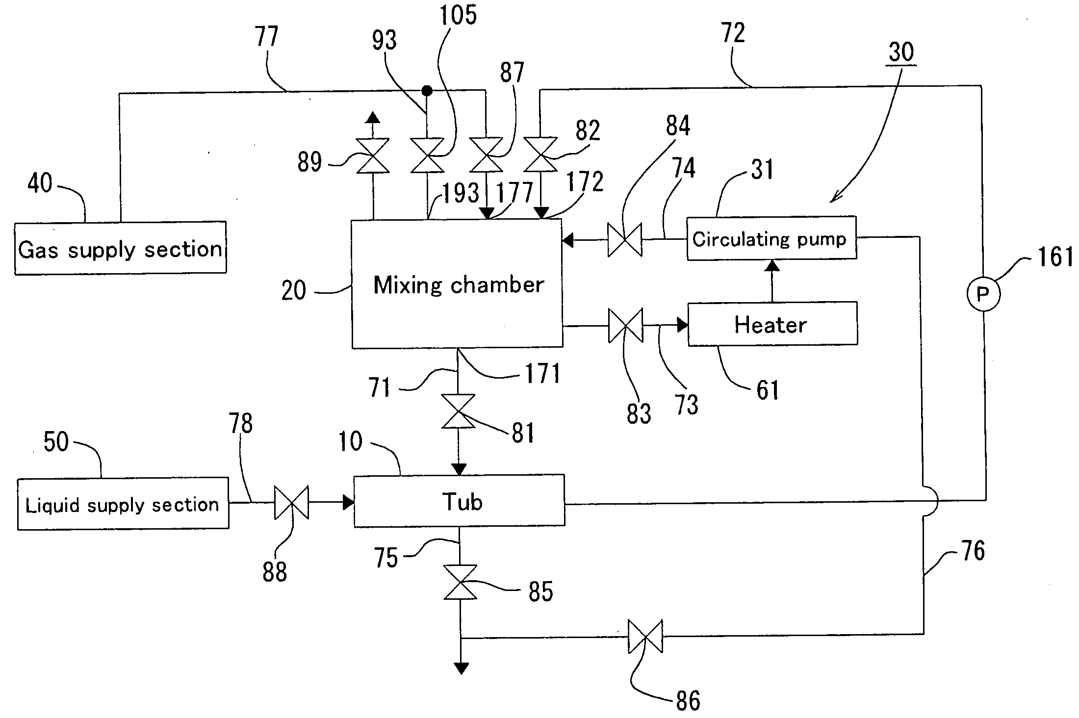
[0049]FIG. 1 is an illustrative diagram which shows schematically the flow of the gas and liquid of the bath fluid mixing apparatus which is related to Embodiment 1 of the present invention.

[0050] The bath fluid mixing apparatus which is related to Embodiment 1 of the present invention provides a tub 10, a mixing chamber 20, a liquid supply path 71 for supplying liquid to tub 10 from mixing chamber 20, a liquid pipe 72 (liquid recover path) for recovering the liquid in the mixing chamber 20 from the tub 10, and a liquid supply section 50 which supplies liquid to the tub 10 by means of the pipe 78 in order to supply liquid in the circulating path of the liquid which arrives at the mixing chamber 20 by means of the supply path 71 from the mixing chamber 10 and the tub 10 and the pipe 72, the gas supply section 40 which supplies gas to the mixing chamber 20 by means of a pipe 77 (gas supply path), and the circulating means 30 for mixing the liquid and gas in the mixing chamber 10.

[005...

embodiment 2

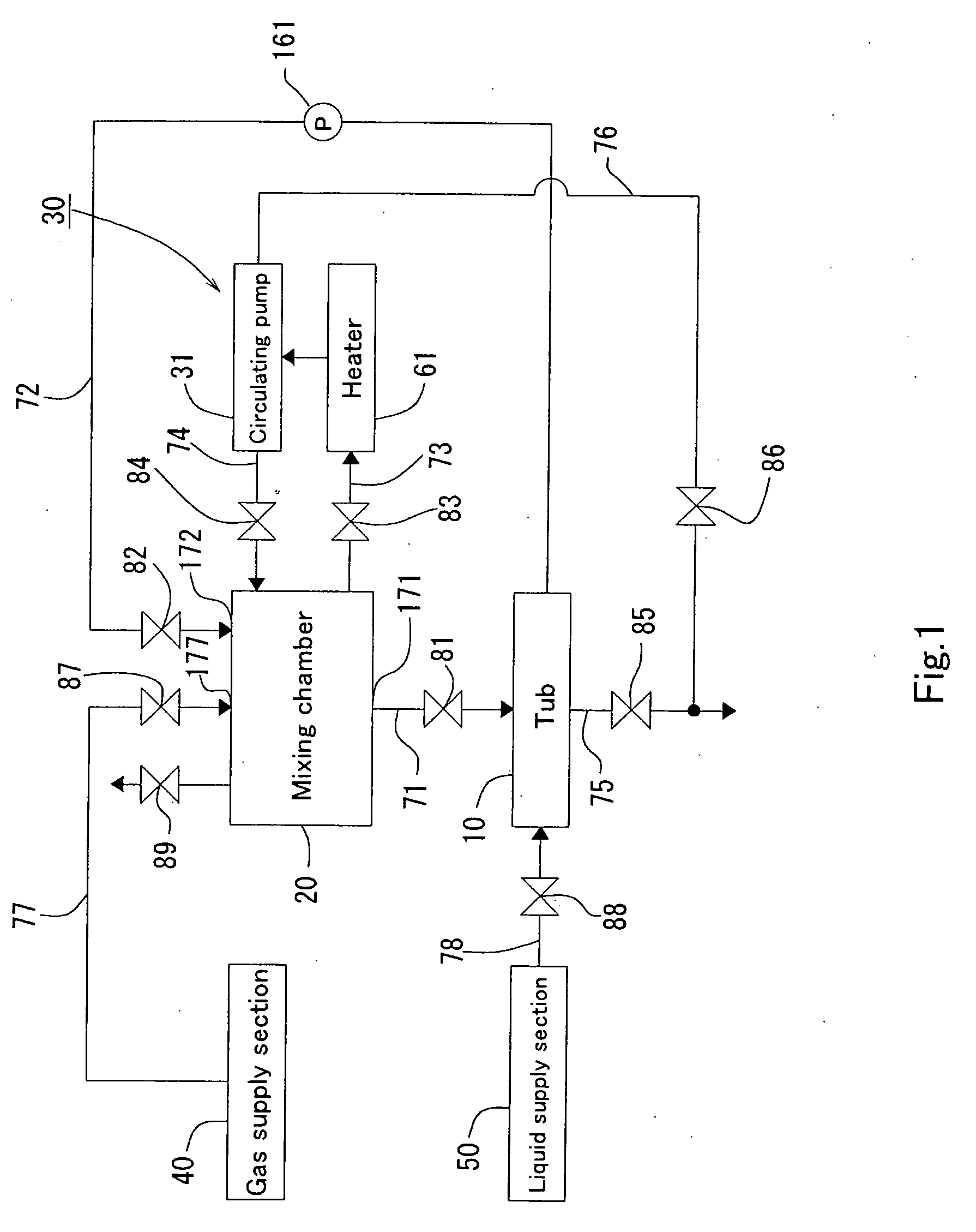
[0075] Below, there's an explanation, based on the drawings, for another embodiment of the present invention. FIG. 7 is a diagram which schematically shows the flow of the gas and liquid of the bath fluid mixing apparatus which is related to the present invention.

[0076] The bath fluid mixing apparatus which is related to the Embodiment 1 of the present invention becomes a structure in which there can be separate connections of the pipe 72 of the pipe 77 to the mixing chamber 20 and for the bath fluid mixing apparatus which is related to Embodiment 2 of the present invention, pipe 77 is connected to pipe 72, and only pipe 72 is connected to a liquid inlet 172′ of the mixing chamber 20 as a common inlet. This difference in connection represents the difference between Embodiment 2 and Embodiment 1. In addition, in order to control gas flow and liquid flow at a junction 72′ (preventing backflow at the junction 72′), an open close valve 82′ and an open close valve 87′ are provided in the...

embodiment 3

[0083]FIG. 9 is a flow diagram which shows the mixing process of the liquid and gas according to the bath fluid mixing apparatus which is related to Embodiment 3 of the present invention. In addition, FIGS. 10-12 are explanatory diagrams which show the border of the mixing chamber 20 for the mixing process.

[0084] When there is mixing of the warm water and carbon dioxide by using the bath fluid mixing apparatus which is related to Embodiment 3 of the present invention, first, there is release of the open close valve 88, and supply of warm water to the tub 10 from the liquid supply section 50 (step S31). If the warm water which was supplied to the tub 10 from the liquid supply section 50 exceeds a prescribed amount, the open close valve 88 closes (steps S32 and S33).

[0085] As shown in FIG. 10, along with releasing the open close valves 82 and 101, there is drawing of air from above the mixing chamber 20 by means of the pipe 91, there is supply of liquid to the mixing chamber 20 from ...


PUM

PropertyMeasurementUnit
Pressureaaaaaaaaaa
Flow rateaaaaaaaaaa
Lengthaaaaaaaaaa

Abstract

A fluid mixing device for a tub includes a closed mixing chamber having: a liquid inlet for introducing liquid into the mixing chamber; a gas inlet for introducing gas into the mixing chamber; and a gas-containing liquid outlet for discharging gas-containing liquid from the mixing chamber to a tub.

Description

BACKGROUND OF THE INVENTION [0001] 1. Field of the Invention [0002] The present invention generally relates to a fluid mixing device for a tub which mixes gas and liquid in order to supply a tub. [0003] 2. Description of the Related Art [0004] The device in Japanese Patent Laid-open No. 2001-145676 is known as a device which mixes gas with liquid to supply this kind of tub. The device disclosed in Japanese Patent Laid-open No. 2001-145676 provides a tub, a jet nozzle which sprays a jet flow to a tub, and an air intake which connects to the jet nozzle by means of an air flow pipe. Thus, according to the device disclosed in Japanese Patent Laid-open No. 2001-145676, it is possible to supply liquid which has mixed with the gas in the tub, and it is possible to enhance the effect of a warm bath. [0005] However, for the device disclosed in Patent Reference 1, because there is simply only the supply of gas through the air flow pipe to the liquid which is to be supplied to the tub, it is n...

Claims


Application Information

Patent Timeline
IPC IPC(8): B01F3/04
CPCA61H33/02B01F3/04099A61H33/005A61H33/60B01F23/23E03C1/08E03C1/084
Inventor MASUDA, MASATOSHI
Owner MASUDA MASATOSHI
Why Eureka
Try Eureka