
Multi-phase clock generator and method thereof

a multi-phase clock and generator technology, applied in the direction of generating/distributing signals, pulse manipulation, pulse technique, etc., can solve the problems of low-cost manufacturing processes such as 0.25 m and 0.35 m processes deficient, and cannot be used hardly, and the manufacturing process is limited

Active Publication Date: 2006-09-21
REALTEK SEMICON CORP
View PDF4 Cites 21 Cited by
  • Summary
  • Abstract
  • Description
  • Claims
  • Application Information

AI Technical Summary

Benefits of technology

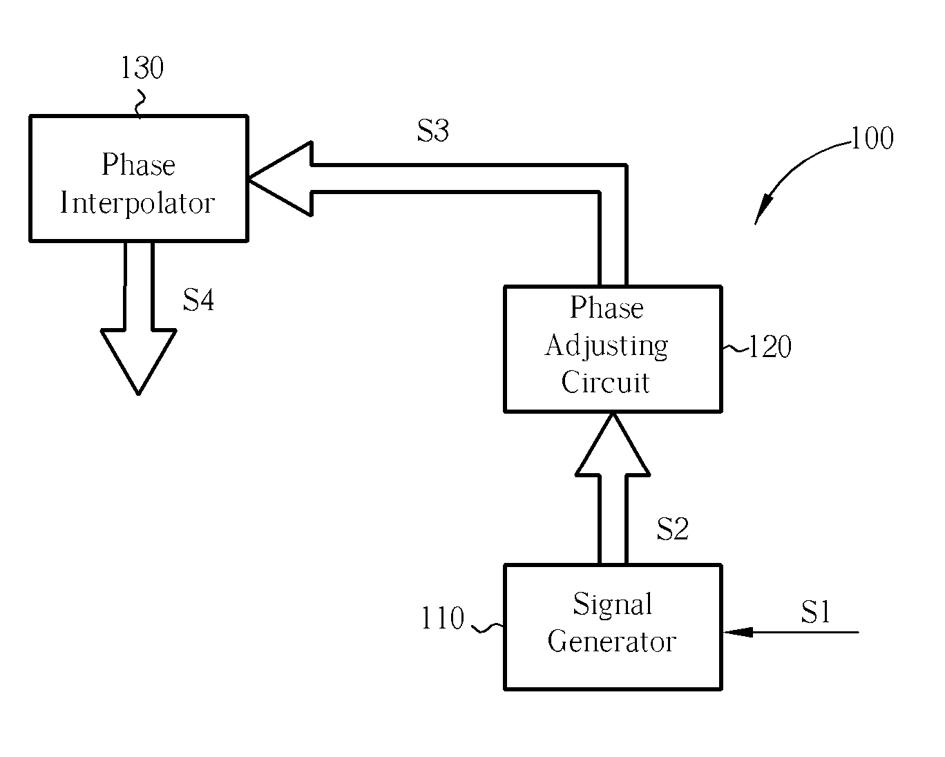
[0006] According to an embodiment of the claimed invention, a multi-phase clock generator is disclosed. The multi-phase clock generator generates a set of multi-phase clock signals, and the multi-phase clock generator includes a signal generator, a phase adjusting circuit, and a phase interpolator. The signal generator generates a plurality of first clock signals according to a reference clock signal. The phase adjusting circuit, which is a phase rotator or a phase selecting circuit, which are coupled to the signal generator, receives the first clock signals and adjusts the phases of the first clock signals according to a control signal to generate a plural

Problems solved by technology

For a large system-on-a-chip (SOC), the manufacturing process is limited primarily by the manufacturing process of the silicon intellectual property (SIP) adopted by the SOC.
When the data transmission rate is as high as or higher than the giga-Hertz (G-bit / sec) level, low-cost manufacturing processes such as 0.25 μm and 0.35 μm processes become deficient and can hardly be utilized.

Method used


Image

  • Multi-phase clock generator and method thereof
  • Multi-phase clock generator and method thereof
  • Multi-phase clock generator and method thereof

Examples


Embodiment Construction

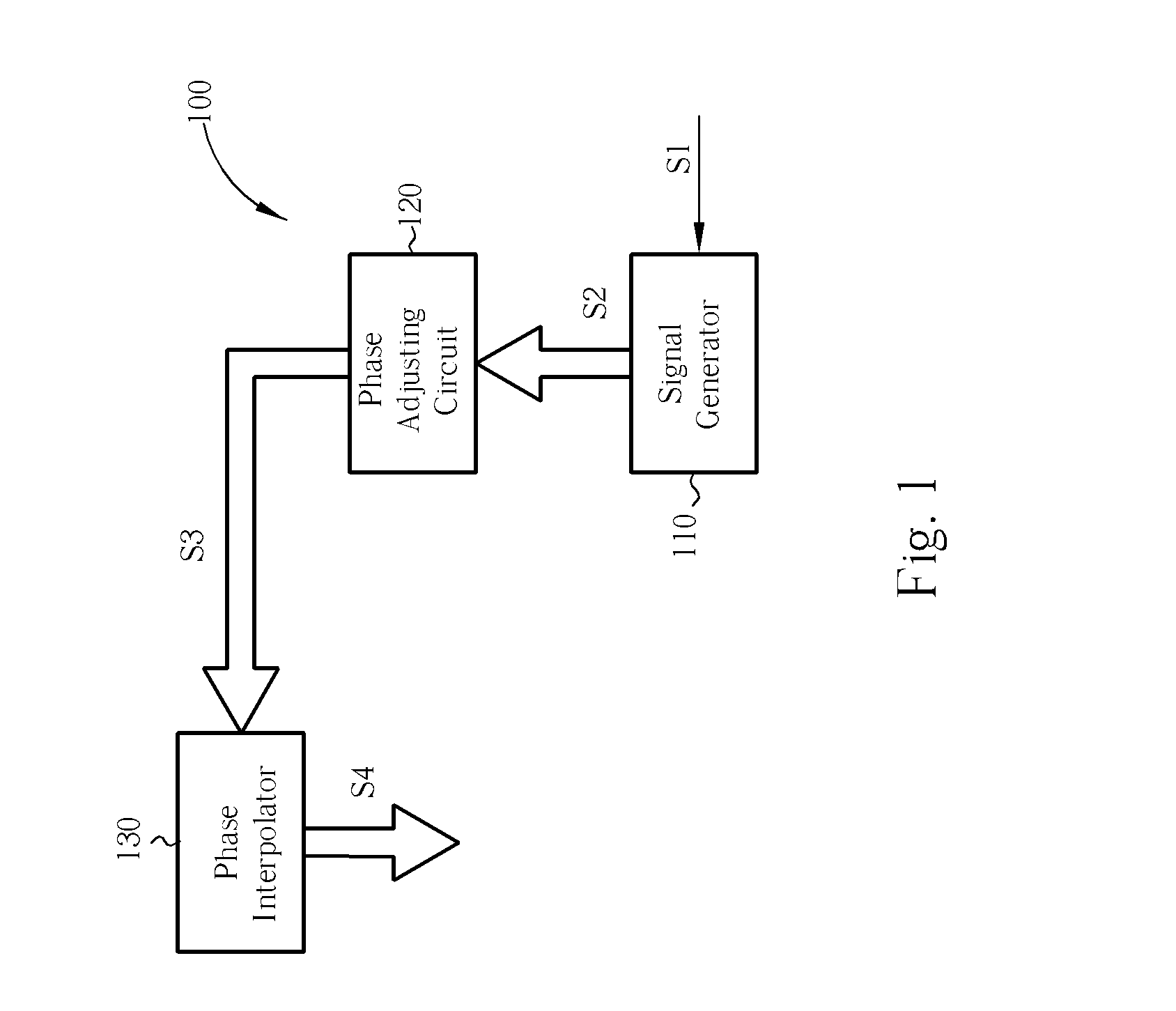
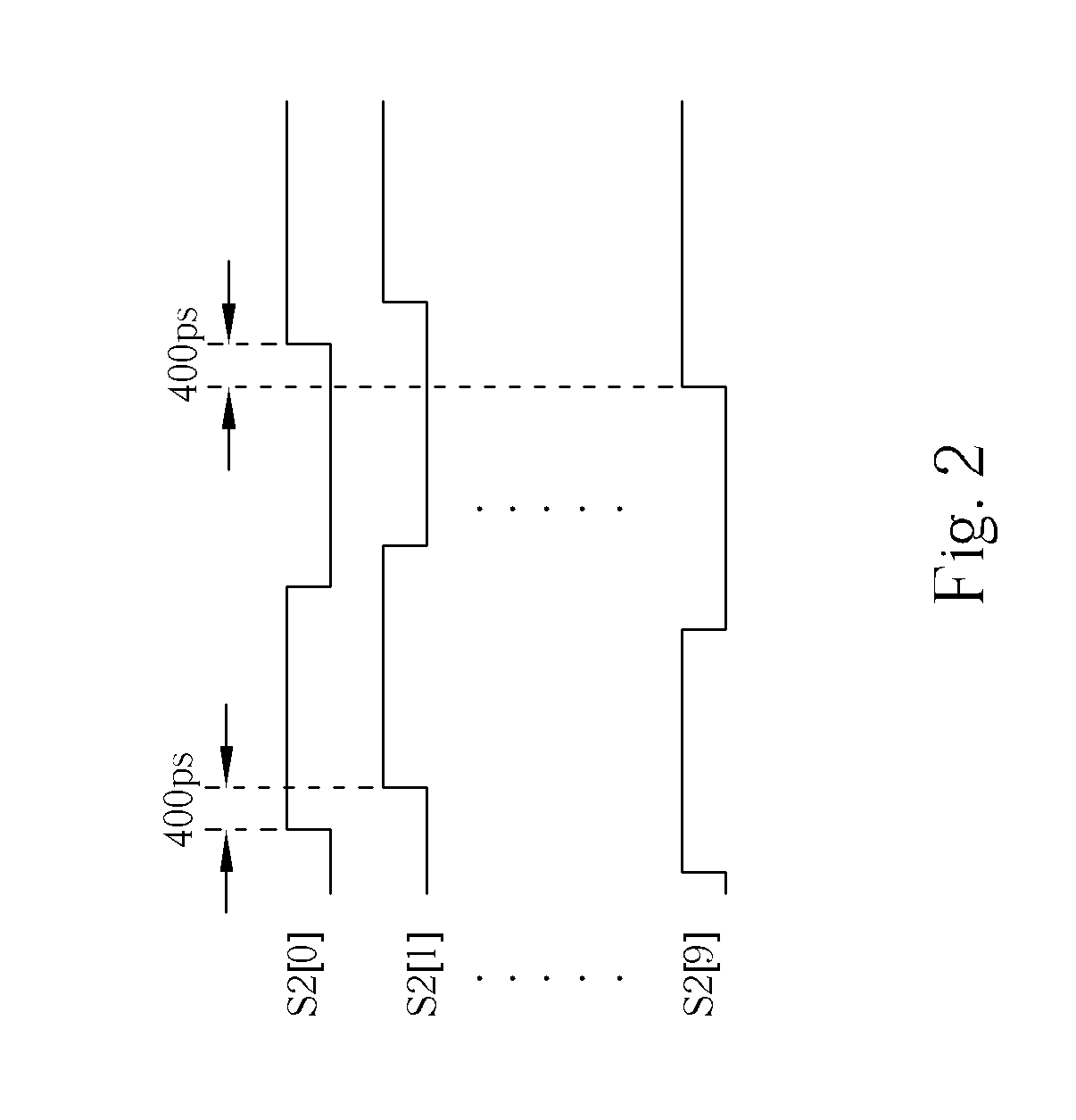
[0015]FIG. 1 shows a multi-phase clock generator 100 according to the first embodiment of the present invention. As shown in FIG. 1, the multi-phase clock generator 100 includes a signal generator 110, a phase adjusting circuit 120, and a phase interpolator 130. In this embodiment, the signal generator 110 receives a reference clock signal S1 and generates a plurality of clock signals S2. The clock signals S2 include a plurality of signals that have the same frequency and are each delayed by a specific and constant phase difference. In other words, the result when graphed on a timing diagram forms a ladder or step-like appearance. The phase adjusting circuit 120 can simultaneously shift all of the phases of the clock signals S2 by advancing or delaying the phases by a specific period. The clock signals S2 are phase shifted into the clock signals S3, which also include a plurality of signals. Then the clock signals S3 are transmitted to the phase interpolator 130. The phase interpola...


PUM


Abstract

A multi-phase clock generator for generating a set of multi-phase clock signals is disclosed. The multi-phase clock generator includes a signal generator, a phase adjusting circuit, and a phase interpolator. The signal generator generates a plurality of first clock signals according to a reference clock signal. The phase adjusting circuit, which is a phase rotator or a phase selecting circuit and coupled to the signal generator receives the first clock signals and adjusts the phases of the first clock signals according to a control signal to generate a plurality of second clock signals. The phase interpolator, which is coupled to the phase adjusting circuit, interpolates the second clock signals to generate the set of multi-phase clock signals.

Description

DESCRIPTION Background of the Invention [0001] 1. Field of the Invention [0002] The present invention relates to a data receiving circuit, especially to a multi-phase clock generator and method thereof. [0003] 2. Description of the Prior Art [0004] For a large system-on-a-chip (SOC), the manufacturing process is limited primarily by the manufacturing process of the silicon intellectual property (SIP) adopted by the SOC. If the manufacturing process of each SIP were more flexible, the difficulty and time in exploiting an SOC could be reduced. For a common high-speed serial link, data reception and transmission are frequently achieved in the following ways: full-rate reception and transmission, half-rate reception and transmission, or multi-phase over-sampling reception and transmission. The former two methods require a full or a half transmission rate for the operating clock of the chip. When the data transmission rate is as high as or higher than the giga-Hertz (G-bit / sec) level, lo...

Claims


Application Information

Patent Timeline
IPC IPC(8): H03B27/00
CPCG06F1/06H03B27/00
Inventor LEE, AN-MING
Owner REALTEK SEMICON CORP
Learn More