Probe for electronic clinical thermometer

Active Publication Date: 2006-09-21
ISHIZUKI ELECTRONICS
View PDF1 Cites 19 Cited by
  • Summary
  • Abstract
  • Description
  • Claims
  • Application Information

AI Technical Summary

Benefits of technology

[0031] According to the probe for the electronic clinical thermometer, since the temperature sensor including the two thin-film heat-sensitive elements formed on one substrate is inserted into the bottomed metal pipe fitted in the top end of the cylindrical housing and arranged perpendicular to the inner wall of the bottomed metal pipe so as to fix one side edge of the substrate tightly on the inner wall of the bottomed metal pipe, the substrate, on which the two thin-film heat-sensitive elements are mounted, is connected thermally to the inner wall of the bottomed metal pipe. Thereby, when heat to be inputted from the one side edge of the substrate of the temperature sensor fixed tightly on the inner wall of the bottomed metal pipe flows through the substrate, temperature difference between the two thin-film heat-sensitive elements formed with a predetermined distance on the substrate is generated. By applying temperature values measured by the two thin-film heat-sensitive elements into the heat conduction equation, the deep body temperature can be predicted. The temperature can be given faster than a usual clinical thermometer without waiting the sensor to reach in heat balance.
[0032] The one side edge of the substrate, in the area of which the first thin-film heat-sensitive element is formed, is fixed tightly on the inner wall of the bottomed metal pipe to be arranged at the upstream side of heat flow, so that the heat flow from the bottomed metal pipe can be conducted securely through the substrate to the two thin-film heat-sensitive elements.
[0033] According to the probe for the electronic clinical thermometer, the temperature sensor structured by the one substrate, on which the two thin-film heat-sensitive elements are formed, is fixed on

Problems solved by technology

It is very difficult to wire lead wires in such a narrow room in the small probe like a probe for clinical thermometer, and to provide and fix the flexible printed circuit board in the metal case so as to roll up it and touch it thermally to the

Method used


Image

  • Probe for electronic clinical thermometer
  • Probe for electronic clinical thermometer
  • Probe for electronic clinical thermometer

Examples


Embodiment Construction

[0043] An embodiment of a probe for an electronic clinical thermometer according to the present invention will be described with reference to figures.

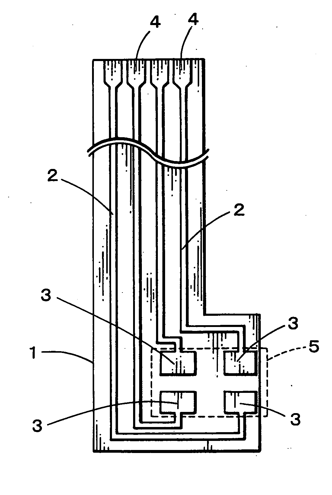
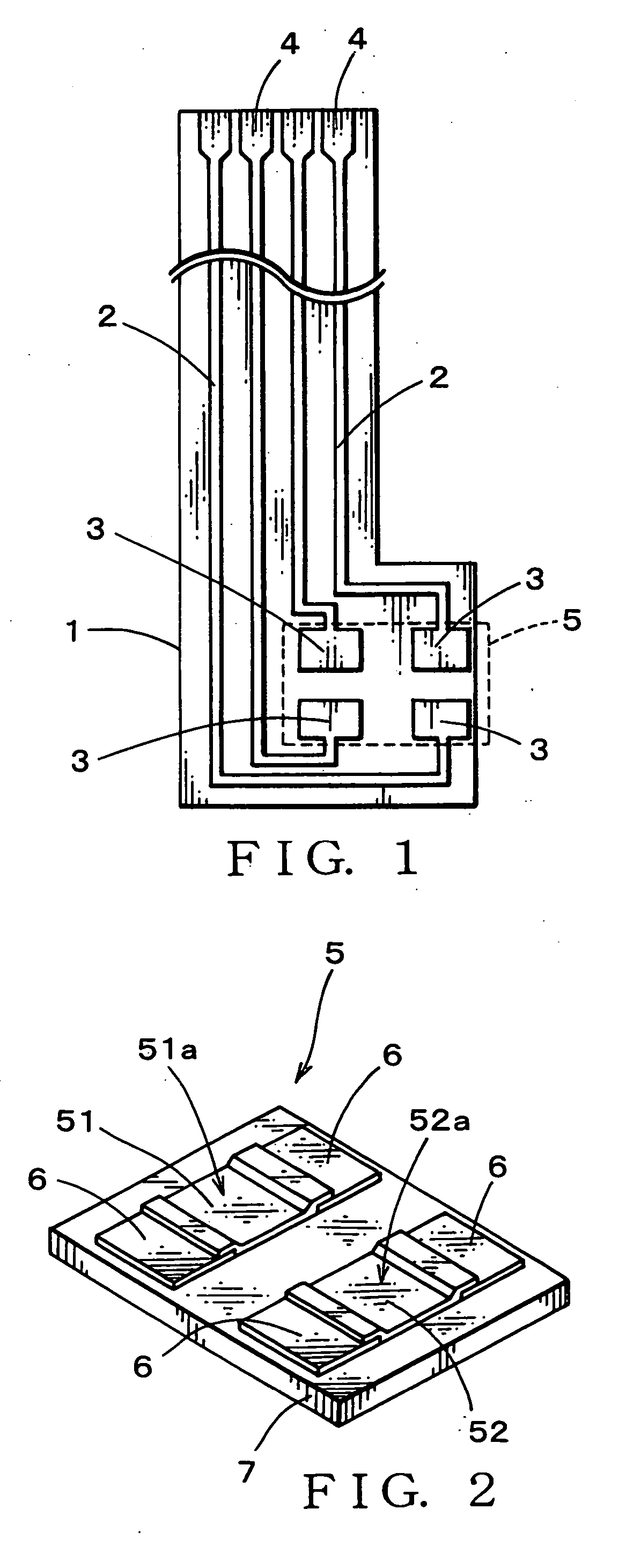
[0044]FIG. 1 shows a shape of a printed wiring board used in the probe for the electronic clinical thermometer of the present invention. A film-like board 1 is made of one of polyimide resin, polyethylene resin, polyester resin and the like, and a wiring pattern 2 made of a conductive foil is formed on a surface of the board. The wiring pattern 2 is provided at one end thereof with lands 3 for electrically connecting with electrodes 6 of the thin-film heat-sensitive elements 51a, 52a. The wiring pattern 2 is provided at the other end thereof with output terminals 4 leading output of the thin-film heat-sensitive elements through the lands 3 and being connected with a succeeding electronic circuit. In the printed wiring board 1, the wiring pattern, a area of which shall be covered for insulation, excluding the lands 3 and the output ter...


PUM


Abstract

Providing a probe for an electronic clinical thermometer, which can measure a surface temperature and a deep body temperature of a human body securely in short time, the probe includes a cylindrical housing, a bottomed metal pipe fitted into a top end of the cylindrical housing, and a substrate having two thin-film heat-sensitive elements arranged perpendicularly on an inner wall of the bottomed metal pipe so as to fix one side edge of the substrate tightly on the inner wall. By measuring heat flux between the two thin-film heat-sensitive elements, the surface and the deep body temperatures of the human body can be predicted by applying the measured values into a heat conduction equation without waiting the sensor to reach in heat balance.

Description

REFERENCE TO RELATED APPLICATIONS [0001] This application claims the benefit of Japanese Patent Application No. 2005-074305 filed on Mar. 16, 2005.BACKGROUND OF THE INVENTION FIELD OF THE INVENTION [0002] This invention relates to a probe for an electronic clinical thermometer, especially a structure of a temperature sensor including a thin-film thermistor, which is provided at a top end of the probe for measuring heat flux to predict a temperature of an object to be measured, especially a body temperature of a human body at any point from a surface to a deep part body of a human body. DESCRIPTION OF THE RELATED ART [0003] A usual method of measuring temperatures, including body temperatures, is performed by use of heat conduction, heat convection or heat radiation. The method requires a condition that the temperature sensor and the object to be measured should be in heat balance. Thereby, when the object to be measured has low heat conductivity, reaching in heat balance requires mu...

Claims


Application Information

Patent Timeline
IPC IPC(8): G01K17/00
CPCG01K7/42G01K13/002G01K13/20
Inventor KAMIYAMA, JUNTAKADA, SHIGERU
Owner ISHIZUKI ELECTRONICS
Why Eureka
Try Eureka