Adaptive pulse shape control

a pulse shape and control technology, applied in the direction of electromagnetic transmission, link quality based transmission modification, transmission, etc., can solve the problems of long-haul transmission system suffer non-linear distortion, dispersion and self-phase modulation (spm), etc., and achieve the effect of relatively easy measuremen

Inactive Publication Date: 2006-09-21
NEPTUNE SUBSEA IP LTD
View PDF7 Cites 25 Cited by
  • Summary
  • Abstract
  • Description
  • Claims
  • Application Information

AI Technical Summary

Benefits of technology

[0015] It is a further advantage of the present invention that it may adjust both the bias voltage and signal drive level modulation parameters of the optical transmitter on the basis of data collected at a remote optical receiver. Consequently, it is possible for the present invention to adjust the bias voltage and signal drive level parameters in a systematic way to take into account both linear and non-linear degradation of the optical signal in the transmission line.
[0016] Preferably, the optical modulator may be controlled to be under-driven or over-driven in order to produce a pulse shape for optimal transmission.
[0017] Preferably, the optical modulator is a Mach-Zehnder (MZ) interferometer. MZ modulators have a sinusoidal transfer function and in the present invention the bias voltage and signal drive level are controlled to distort the pulse shape produced by the MZ modulator.
[0018] The present invention may be used in conjunction with conventional methods of optimising optical transmitter output. Conventional methods may be adopted for back-up purposes or to additionally refine

Problems solved by technology

The component is well established and applicable but has some detrimental drift and ageing characteristics that require external control to maintain peak performance.
However, in practice long haul transmission systems suffer from non-linear distortion, dispersion and self-phase modulation (SPM) effects.
However, it is not operationally or economically practical to fine tune the launch and receive dispersion values of every channel in a

Method used


Image

  • Adaptive pulse shape control
  • Adaptive pulse shape control
  • Adaptive pulse shape control

Examples


Embodiment Construction

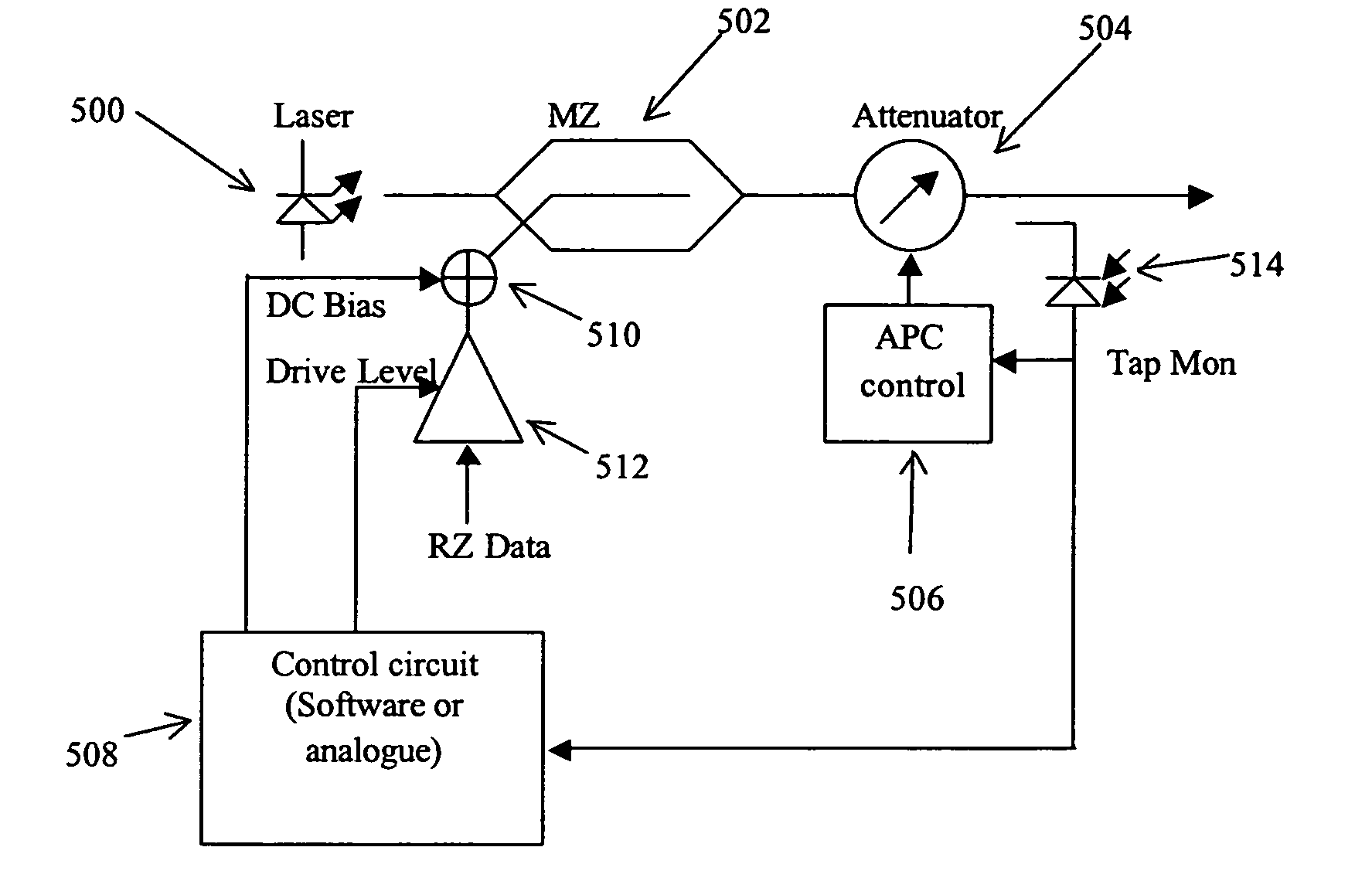
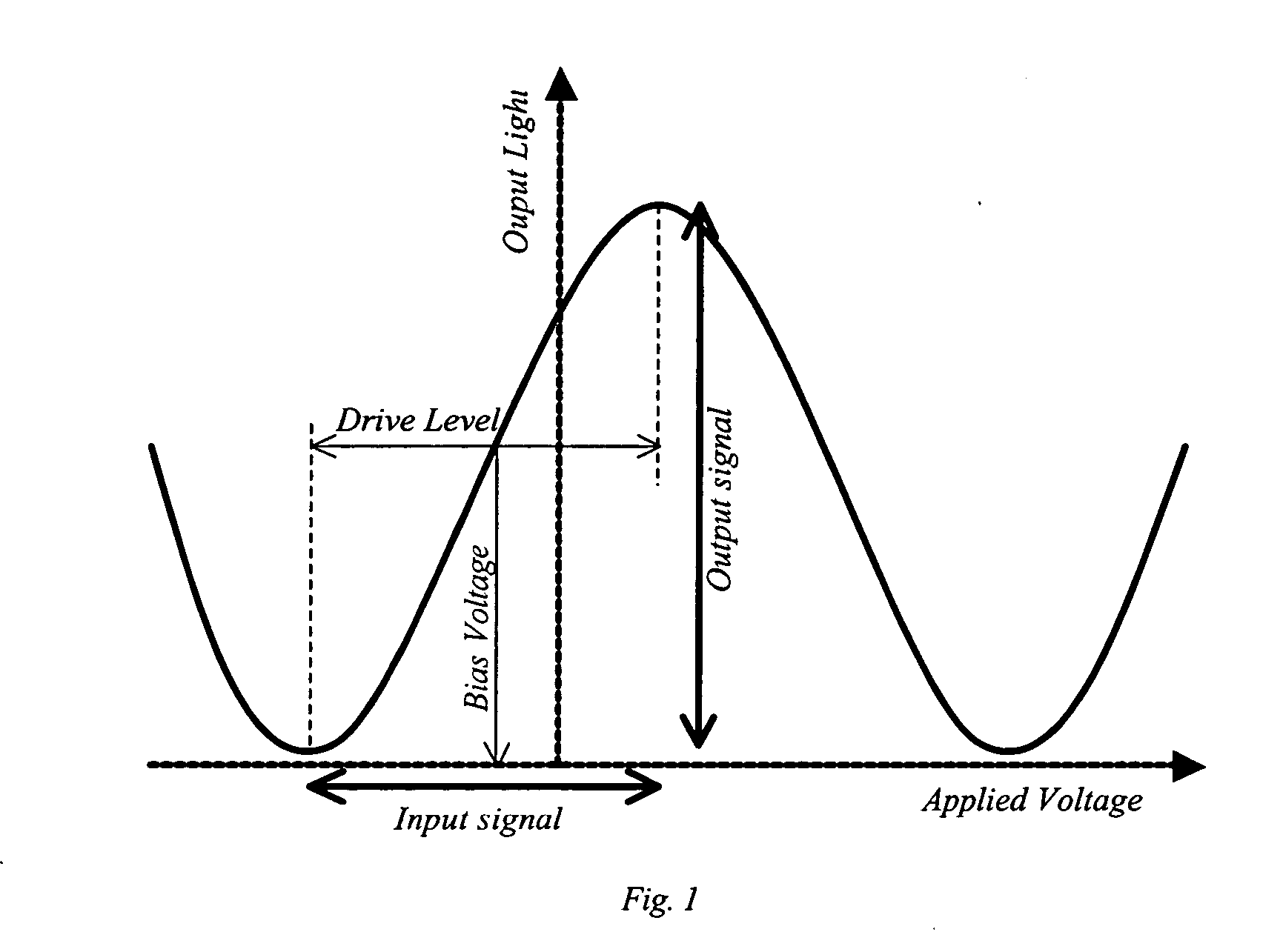
[0037] MZ interferometers are commonly used in optical transmission systems. FIG. 1 shows how the output signal of a typical MZ varies with the applied voltage. As shown, the MZ is normally driven around a bias voltage by a drive level. The bias voltage is typically set for the mid-point of output power (half way between a maximum and a minimum shown in the curve shown in FIG. 1).

[0038] The drive level is then set to maximise the extinction ratio of the signal. The extinction ratio (ER) of an optical signal is a commonly used parameter. It is defined as (light level at ‘1’—light level at ‘0’) / (light level at ‘0’). As such, to maximise the ER the drive level is chosen to drive the MZ across its full characteristics. In this way, a maximally open data eye is achieved. FIG. 4a illustrates the resulting optical signal when the modulator is driven in this way. Conventional techniques try to ensure that this pulse shape is retained throughout the life of the transmitter.

[0039] MZ interf...


PUM


Abstract

A method, apparatus, and computer program product are provided for optimising the pulse shape of optical signals output from an optical transmitter. The optical transmitter includes an optical modulator controlled by a bias voltage and a signal drive level, wherein the bias voltage and signal drive level are controlled automatically in a systematic way in dependence on one another to adapt the pulse shape of an optical output signal for optimal transmission over a transmission line.

Description

CROSS-REFERENCE TO RELATED APPLICATIONS [0001] This application claims the benefit of U.S. Provisional Application Ser. No. 60 / 659,293, filed Mar. 7, 2005, which is incorporated herein by reference.BACKGROUND TO THE INVENTION [0002] Optical transmitters for long haul applications at multi-gigabit rates are usually implemented by use of a Lithium Niobate Mach Zehnder (MZ) modulator to gate continuous wave (CW) laser light. The component is well established and applicable but has some detrimental drift and ageing characteristics that require external control to maintain peak performance. [0003] Conventionally these control circuits are arranged to optimise optical extinction ratio and maintain a maximum modulation depth. Typically, drive level and bias voltage are adjusted separately and the effect monitored by sampling the average transmitter output signal power. Conventionally, the AC coupled input signal drive voltage summed with a DC bias is arranged to exercise the modulator from...

Claims


Application Information

Patent Timeline
IPC IPC(8): G02F1/01
CPCG02F1/0123G02F1/225G02F2203/26H04B10/505H04B10/50572H04B10/50575H04B10/508H04L1/0001H04L1/0026H04L25/03834G02F1/2252H03G1/02
Inventor WEBB, STEPHEN MICHAELOBERLAND, RICHARD
Owner NEPTUNE SUBSEA IP LTD
Why Eureka
Try Eureka