Autofocus system

Active Publication Date: 2006-09-21
FUJI PHOTO OPTICAL CO LTD
View PDF1 Cites 45 Cited by
  • Summary
  • Abstract
  • Description
  • Claims
  • Application Information

AI Technical Summary

Benefits of technology

[0008] Thus, a method in which the AF area automatically tracks a moving target subject is effective because the labor of the operator to adjust the location of the AF area is no longer required. For example, a so-called pattern matching technology is known as a method that detects a specific reference pattern image within a source image. By applying that technology it is possible to detect an image of a specific target subject within a captured image, and it is possible to have the AF area track the target subject by moving the AF area to the position of the detected target subject.
[0011] Accordingly, it is possible to reduce the possibility of erroneously detecting a target subject by setting a high threshold value to set stringent conditions for determining the existence of a pattern. In this specification, assuming that the degree of matching for determining that an image that matches a reference pattern image was detected (pattern exists) within a source image in pattern matching is referred to as the “pattern matching sensitivity” (or simply “sensitivity”), then setting stringent conditions for determining that a pattern exists, i.e. increasing the aforementioned threshold value, refers to increasing the pattern matching sensitivity.
[0013] The present invention was made in light of the above described circumstances, and an object of this invention is to provide an autofocus system that can adequately prevent erroneous detection of a target subject by an automatic tracking function that automatically tracks a target subject as a focus object by AF on a screen.
[0016] According to the first aspect of this invention, when a correlation value for a reference pattern image and an image detected among captured images as the image that most matches the reference pattern image that was stored as an image of a target subject is equal to or greater than a predetermined threshold value, that image is determined to be an image of the target subject. This invention also makes it possible to change the threshold value. Therefore, according to this invention a suitable threshold value (i.e. sensitivity) can be set in accordance with an imaging situation and erroneous detection of a target subject can be adequately prevented.
[0019] According to the autofocus system of this invention, erroneous detection of a target subject by an automatic tracking function can be adequately prevented.

Problems solved by technology

A problem thus exists in that the operation requires the labor and attention of the operator.
However, when the image of a target subject on a screen showing captured images changed significantly, the risk that a subject other than the target subject will be erroneously detected as the target subject increases significantly.

Method used


Image

  • Autofocus system
  • Autofocus system
  • Autofocus system

Examples


Embodiment Construction

[0024] Hereunder, preferred embodiments of the autofocus system of this invention are described in detail in accordance with the attached drawings.

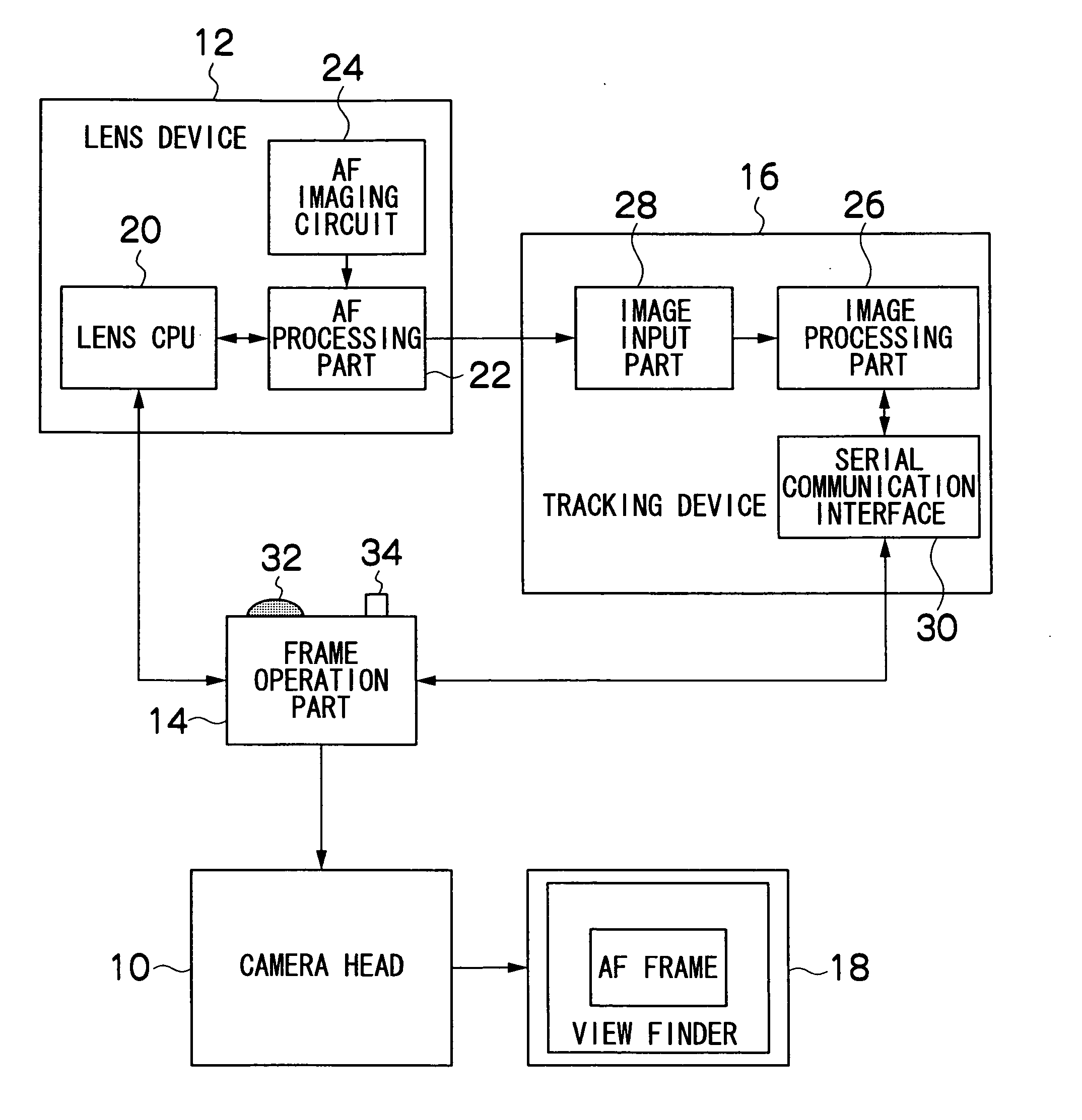
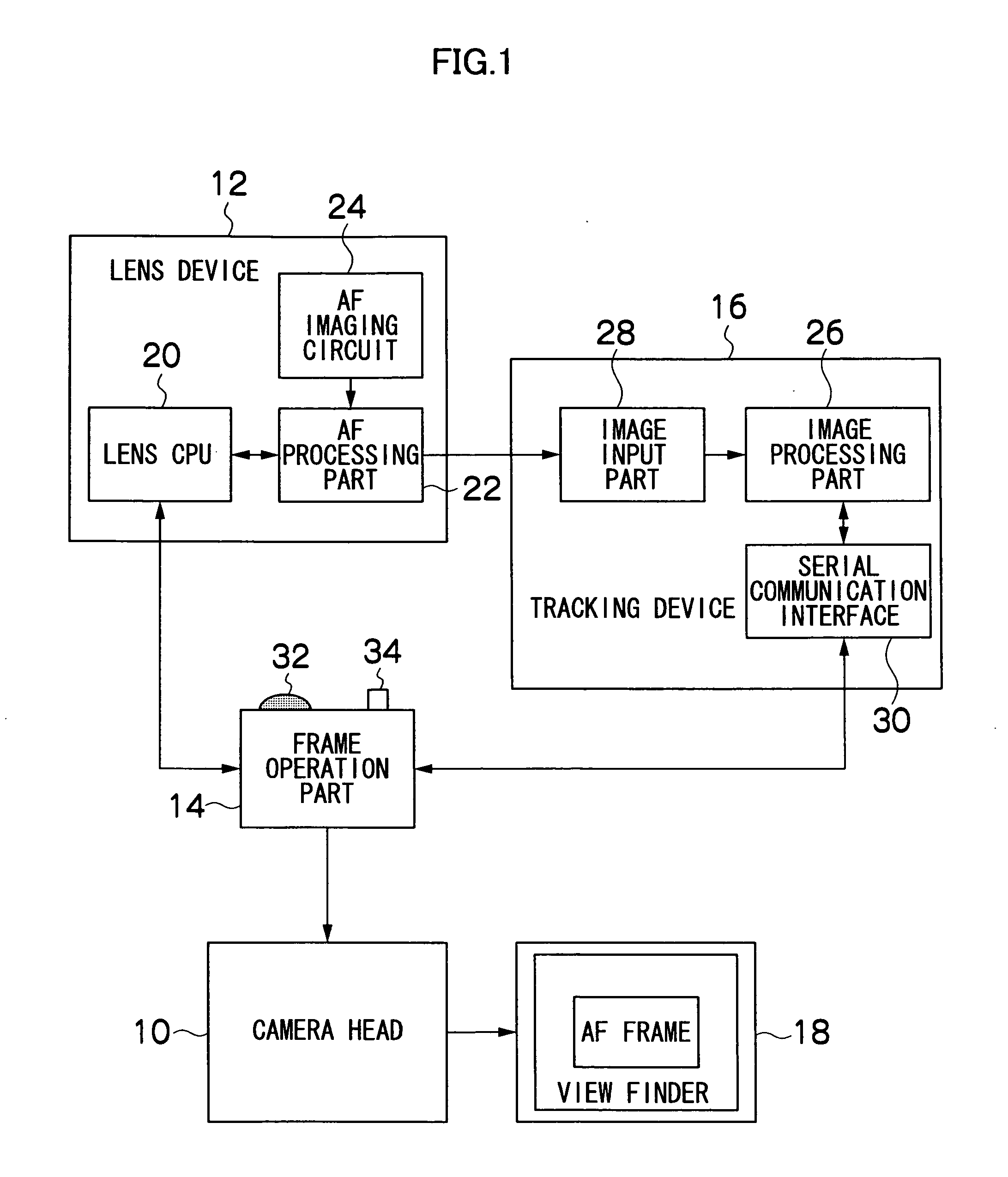
[0025]FIG. 1 is a block diagram illustrating the overall configuration of an imaging system which applies the autofocus system of this invention. The imaging system shown in the figure is, for example, an imaging system used in imaging by a television camera for broadcasting. The figure shows a camera head 10 for which it is possible to exchange lenses, a lens device 12 which is equipped with a taking lens (optical system) that is mounted in a lens mount of the camera head 10, a frame operation part 14, and a tracking device 16 and the like.

[0026] On the camera head 10 is mounted an image pickup device (for example, a CCD) and a required signal processing circuit or the like. An image formed by the taking lens of the lens device 12 undergoes photoelectric conversion by the image pickup device and is then subjected to required signal pro...


PUM


Abstract

An autofocus system comprising: an imaging device which images a subject image that was formed by an optical system; a matching image detection device which detects an image that most matches a reference pattern image that was previously stored as an image of a target subject to focus on among captured images that were imaged by the imaging device; a determining device that determines that an image of the target subject was detected among the captured images when a correlation value which indicates a degree of matching of an image detected by the matching image detection device with respect to the reference pattern image is equal to or greater than a predetermined threshold value and determines that an image of the target subject was not detected among the captured images when the correlation value is less than the threshold value; a changing device which changes the threshold value in the determining device; and an autofocus device which, only in a case where the determining device determined that an image of the target subject was detected, takes a position, on the screen showing captured images, of an image that was detected by the matching image detection device as a position of the target subject to focus on and performs focus adjustment of the optical system such that a target subject in the position is in focus.

Description

BACKGROUND OF THE INVENTION [0001] 1. Field of the Invention [0002] The present invention relates to an autofocus system, and more particularly to an autofocus system comprising an automatic tracking function that tracks a desired target subject as a focus object on a camera screen showing captured images. [0003] 2. Description of the Related Art [0004] In imaging systems such as television cameras that convert images of a subject from an image pickup device (CCD or the like) into electrical signals (image signals), a contrast system is generally employed as an autofocus (hereunder, abbreviated as “AF”) system. A contrast system is a system which detects the contrast of a subject image from image signals that were captured by an image pickup device to automatically perform focusing to achieve the optimal focus state by controlling the focus of the taking lens such that the highest contrast is achieved. [0005] In most AF employing a contrast system, the entire subject within the imag...

Claims


Application Information

Patent Timeline
IPC IPC(8): G03B13/30
CPCG01S3/7864H04N5/23212H04N23/673H04N23/675H04N23/635
Inventor YATA, KUNIO
Owner FUJI PHOTO OPTICAL CO LTD
Why Eureka
Try Eureka