Method for detecting a fluid leak in a turbomachine and system for distributing a fluid

a turbomachine and fluid leak detection technology, applied in the field of turbomachines, can solve the problems of damage to the turbomachine, strong temperature rise, and the elements of composite materials that cannot only keep their integrity, and achieve the effect of reducing the detection tim

Active Publication Date: 2015-11-26
SN DETUDE & DE CONSTR DE MOTEURS DAVIATION S N E C M A
View PDF44 Cites 14 Cited by
  • Summary
  • Abstract
  • Description
  • Claims
  • Application Information

AI Technical Summary

Benefits of technology

[0011]The object of the invention is to overcome this drawback and the aim thereof is therefore to provide a method for detecting a high temperature fluid leak in a turbomachine which would enable detecting a high temperature fluid leak in a turbomachine compartment whatever the origin of the leak, and this with a reduced detection time compared with prior art.

Problems solved by technology

Thus, because of the generally high temperature of these pressurized gas fluids, the slightest leak of a pipe in one of these sensitive compartments of the turbomachine can be a problem and damage the turbomachine.
However a leak in the fan compartment of the pressurized air passing in the NAI circuit can lead to a strong temperature rise in this compartment which is likely to exceed 350° C. At these temperatures, said elements of composite material(s) can only keep their integrity on a relatively short lapse of time, typically in the order of 15 s.
However, both methods only partially address the problem of monitoring a high temperature gas fluid leak in a sensitive compartment of the turbomachine.
Indeed, though these methods enable, for example, the detection of a valve that would remain open and which could potentially generate, through this constant communication, a temperature rise in the sensitive compartment, they are not adapted to detect a leak which could be linked to the breakup or disengagement of a duct from the pipe.
This problem is particularly present for the system for distributing a fluid, in particular gas fluid, which comprises the high temperature pressurized air supply pipe of both the aircraft and the starter of the turbomachine and the air supply pipe of the NAI circuit.
However, as already indicated, the fan compartment is particularly sensitive due to the elements of composite material(s) it contains.

Method used


Image

  • Method for detecting a fluid leak in a turbomachine and system for distributing a fluid
  • Method for detecting a fluid leak in a turbomachine and system for distributing a fluid
  • Method for detecting a fluid leak in a turbomachine and system for distributing a fluid

Examples


Embodiment Construction

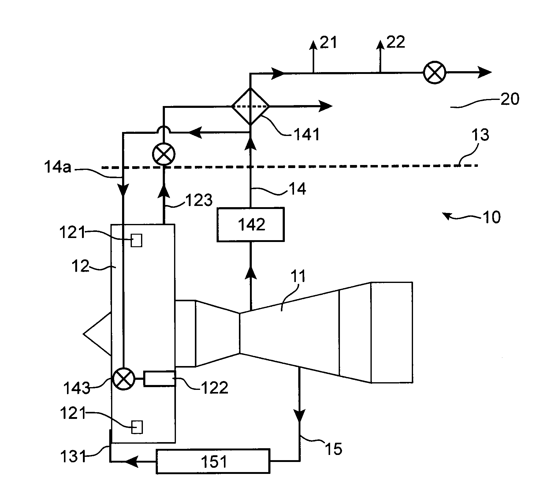
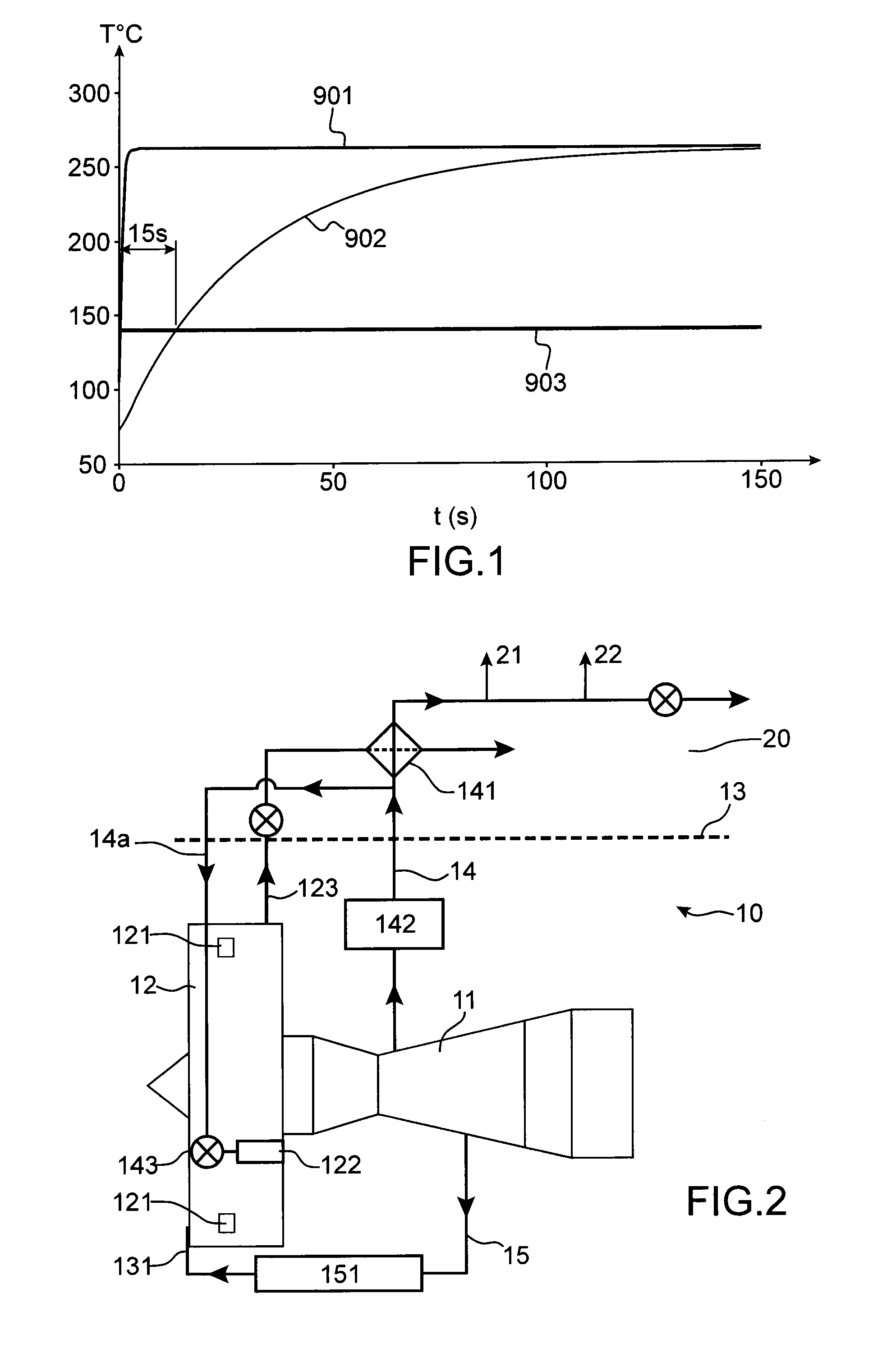
[0069]FIG. 2 schematically shows an exemplary system for distributing a fluid, more precisely pressurized air, according to the invention equipping a turbomachine 10.

[0070]Such a system for distributing a fluid comprises:[0071]a high pressure compressor 11 forming a high temperature pressurized air source,[0072]a fan 12 having a casing which externally delimits a secondary flow stream and outside which a first and a second temperature sensors 121 are fitted to measure the temperature in the fan compartment,[0073]a turbomachine nacelle 13 comprising an inlet scoop 131 of the turbomachine for the air intake in the latter,[0074]a first high pressure pipe 14 to draw out high temperature pressurized air from the high pressure compressor to the aircraft, said first pipe comprising a secondary branch 14a to supply a turbomachine starter 122 with pressurized air,[0075]a second pipe 15 for the nacelle anti-icing 13 and the turbomachine 10 inlet scoop 131,[0076]an engine computer, not shown.

[...


PUM


Abstract

The invention relates to a method for detecting a fluid leak in a turbomachine. The turbomachine comprises a high temperature fluid source, at least one fluid distribution pipe adapted to distribute said fluid to different parts of the turbomachine and/or the aircraft which is intended to be equipped with said turbomachine, a turbomachine compartment in which the distribution pipe is at least partly accommodated, said compartment having in operation a low temperature relative to the high temperature of the fluid supplied by the fluid source. The method comprises the following steps: measuring a temperature variation in the compartment between two instants to obtain a temperature gradient; and detecting a fluid leak if the temperature gradient is greater than or equal to a threshold temperature gradient. The invention further relates to a system for distributing a high temperature fluid for a turbomachine and a turbomachine comprising such a system for distributing a fluid.

Description

TECHNICAL FIELD[0001]The invention relates to the field of turbomachines, and particularly to the field of systems for distributing a fluid equipping such turbomachines.STATE OF PRIOR ART[0002]Systems for distributing especially a pressurized and gaseous fluid in turbomachines generally involve a high number of pipes some of which may be disposed at least partly in sensitive compartments of turbomachines.[0003]Thus, because of the generally high temperature of these pressurized gas fluids, the slightest leak of a pipe in one of these sensitive compartments of the turbomachine can be a problem and damage the turbomachine. This is particularly the case for the Nacelle Anti-Icing (NAI) circuit and the pressurized air supply circuit of the starter, which are partly accommodated in a zone fan compartment radially situated outside the turbomachine fan casing and inside the nacelle.[0004]Indeed, a turbomachine fan, and more particularly the fan compartment, may comprise elements of composi...

Claims


Application Information

Patent Timeline
Patent Type & Authority Applications(United States)
IPC IPC(8): F01D21/00F01D21/12
CPCF01D21/12F01D21/003F01D17/085F02C6/08F02C7/047G01M3/002F05D2270/309F05D2270/303G01M3/025Y02T50/60
Inventor EVERWYN, ALEXANDRE PATRICK JACQUES ROGERRODHAIN, ARNAUD
Owner SN DETUDE & DE CONSTR DE MOTEURS DAVIATION S N E C M A
Why Eureka
Try Eureka