Constructive water resource recycling method

a water resource and construction technology, applied in water conservation, sewage draining, ways, etc., to achieve the effect of efficiently recycling rain, avoiding heat-island effect, and efficiently maintaining water resources for further utilization

Inactive Publication Date: 2006-09-21
CHEN JUI WEN
View PDF8 Cites 36 Cited by
  • Summary
  • Abstract
  • Description
  • Claims
  • Application Information

AI Technical Summary

Benefits of technology

[0007] The primary purpose of the present invention is to provide a constructive water resource recycling method which relates to constructing and drilling a permeable pavement on the ground surface, and burying underground water reservoirs, which include connection of pipelines, drawing the accumulated water to the ground surface via generators of natural power for secondary use such as irrigation, thereby efficiently maintaining the water resource for further utilization.
[0008] The secondary object of the invention is to provide a constructive water resource recycling method, which includes the provision of deep drainage trenches, the side walls of which have water inlets such that the rain can permeate to the underground soil. A drainage band is provided in the soil to serve as a connection of the water reservoirs an respective upper positions thereof. Trench bottoms of permeable paving are provided at pre-determined positions, such that when the surplus rain cannot be drain away through the drainage trenches, it can be permeate down to the underground soil through the permeable trench bottoms to supplement the underground water resource and also avoid water from accumulating on the ground to occur floods. A further object of the invention is to provide a constructive water resource recycling method, which can allow more water contained

Problems solved by technology

However, as the mentioned design can only lead the rain into th

Method used


Image

  • Constructive water resource recycling method
  • Constructive water resource recycling method
  • Constructive water resource recycling method

Examples


Embodiment Construction

[0018] The following descriptions are of exemplary embodiments only, and are not intended to limit the scope, applicability or configuration of the invention in any way. Rather, the following description provides a convenient illustration for implementing exemplary embodiments of the invention. Various changes to the described embodiments may be made in the function and arrangement of the elements described without departing from the scope of the invention as set forth in the appended claims.

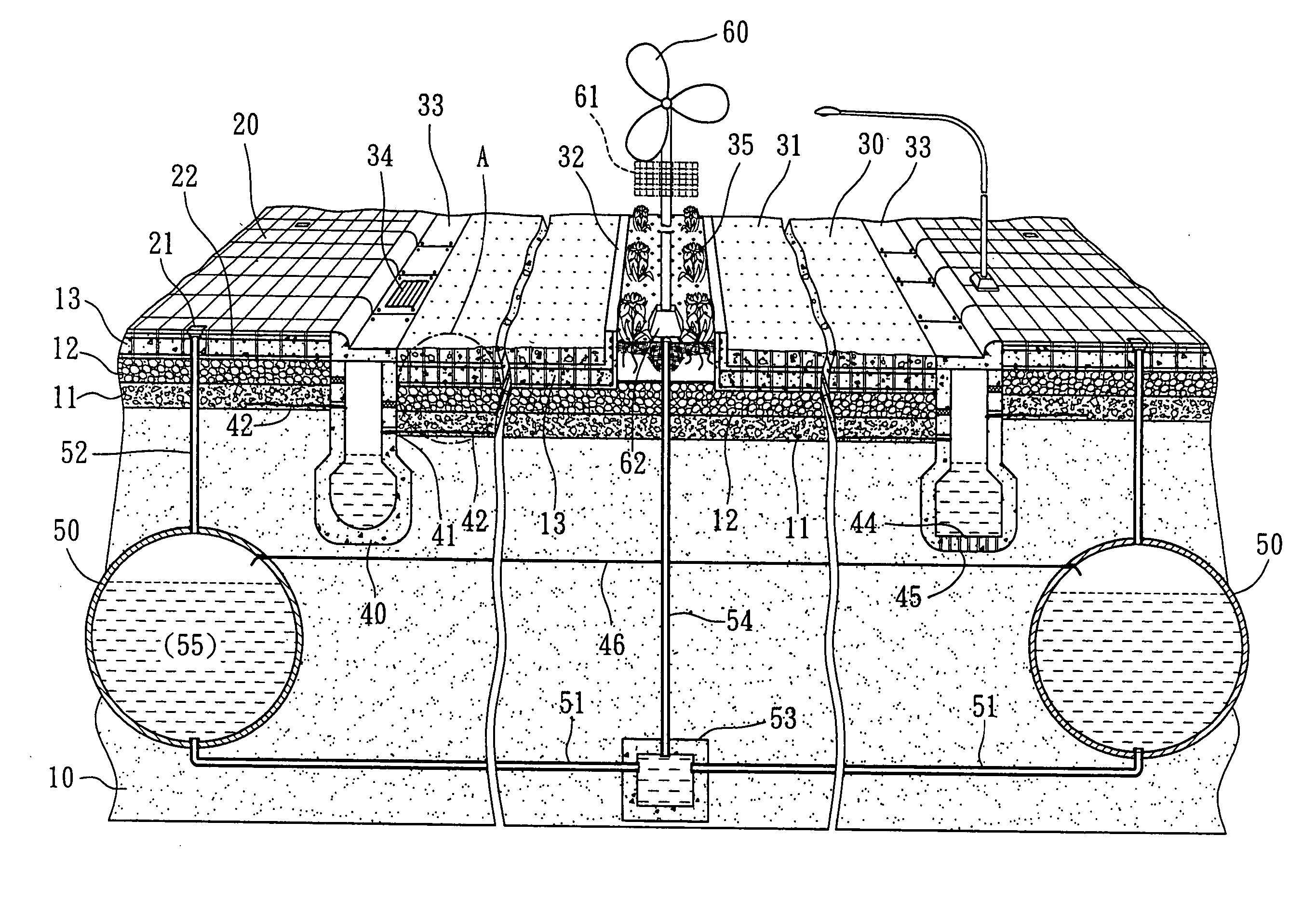
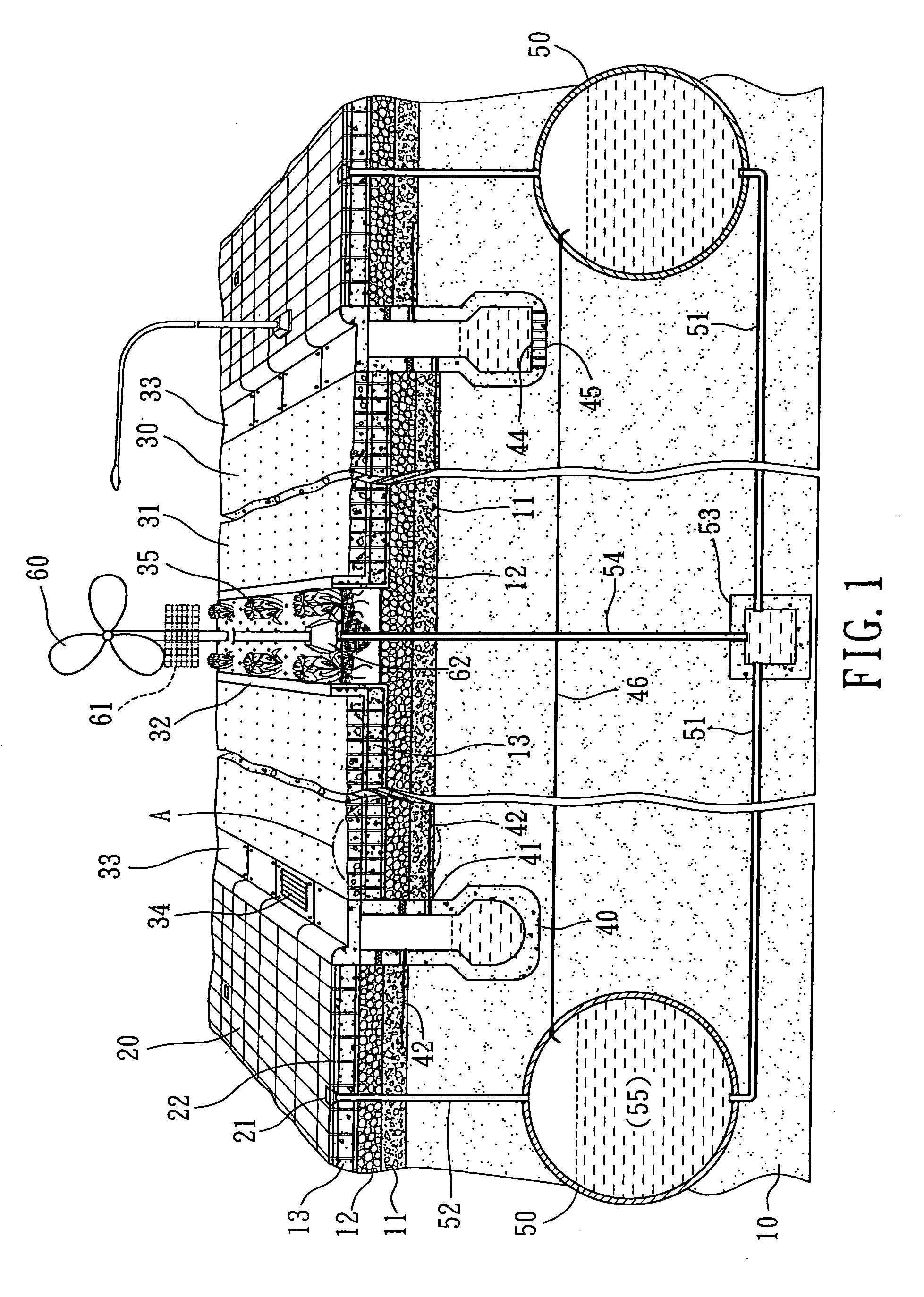
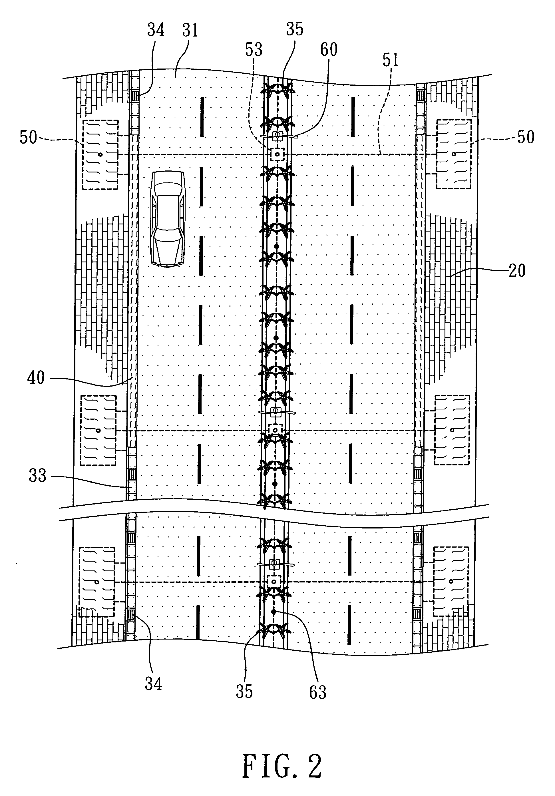
[0019] Referring to FIGS. 1 and 2, the constructive water resource recycling method according to the invention includes digging the underground soil layer 10 and burring pluralities of great-sized water reservoirs 50. Meanwhile, deep drainage trenches 40 are built in the underground soil layer 10 which is paved with a macadam stratum 11 and then an instantly permeable layer 12 composed of macadam, pebbles or sand. A rigid ground surface 13 formed by reinforcing steels and concrete is paved on t...


PUM


Abstract

A constructive water resource recycling method is characterized in that great-sized water reservoirs, each of which has a drainpipe provided above for connecting to the ground surface, are buried in the underground soil; deep drainage trenches are selectively provided under the macadam stratum; the side walls of the deep drainage trenches have water inlets such that the rain can be led down to the soil via drainage bands, while trenches are covered by trench covers; the water contained in the water reservoirs can be drawn by water-drawing pipes to the ground surface for further utilization through a water pump of natural power; the great-sized water reservoirs are covered by soil and macadam stratum, and then an instantly permeable layer which is composed of macadam, pebbles or sand; finally, the instantly permeable layer is covered a concrete pavement and then drilled through to complete a constructive permeable pavement, thereby efficiently recycling the rain for fully utilization.

Description

BACKGROUND OF THE INVENTION [0001] (a) Technical Field of the Invention [0002] The present invention relates to a constructive water resource recycling method, particularly to one that relates to constructing a concrete pavement on a walkway or roadway and drilling through pluralities of permeable holes, thereby accomplishing a constructive permeable pavement. The rain can therefore be instantly led into the underground soil layer for specifically and efficiently collected and accumulated. By way of building pipeline system and providing water pump equipment, the water accumulated in the underground can be drawn up to the ground surface for secondary use. Accordingly, the water resource can be fully utilized to reach the purpose of environmental protection. [0003] (b) Description of the Prior Art [0004] With respect to the construction for a ground surface of an environmental, permeable function of the prior art, the inventor of the present invention disclosed in 1999 “Construction ...

Claims


Application Information

Patent Timeline
IPC IPC(8): E01C11/22
CPCE03B3/03E03F1/002Y02A20/108Y02A20/00
Inventor CHEN, JUI-WEN
Owner CHEN JUI WEN
Why Eureka
Try Eureka