Chained terminals and method of forming chained terminals
- Summary
- Abstract
- Description
- Claims
- Application Information
AI Technical Summary
Benefits of technology
Problems solved by technology
Method used
Image
Examples
first embodiment
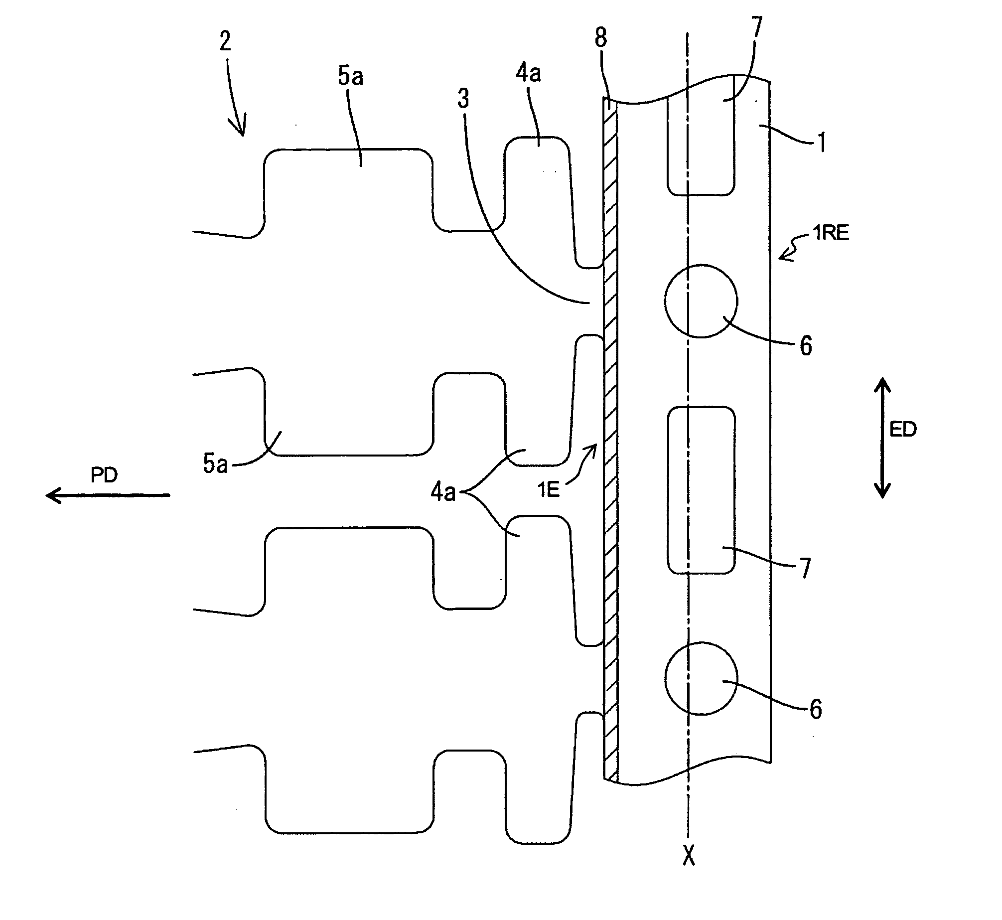
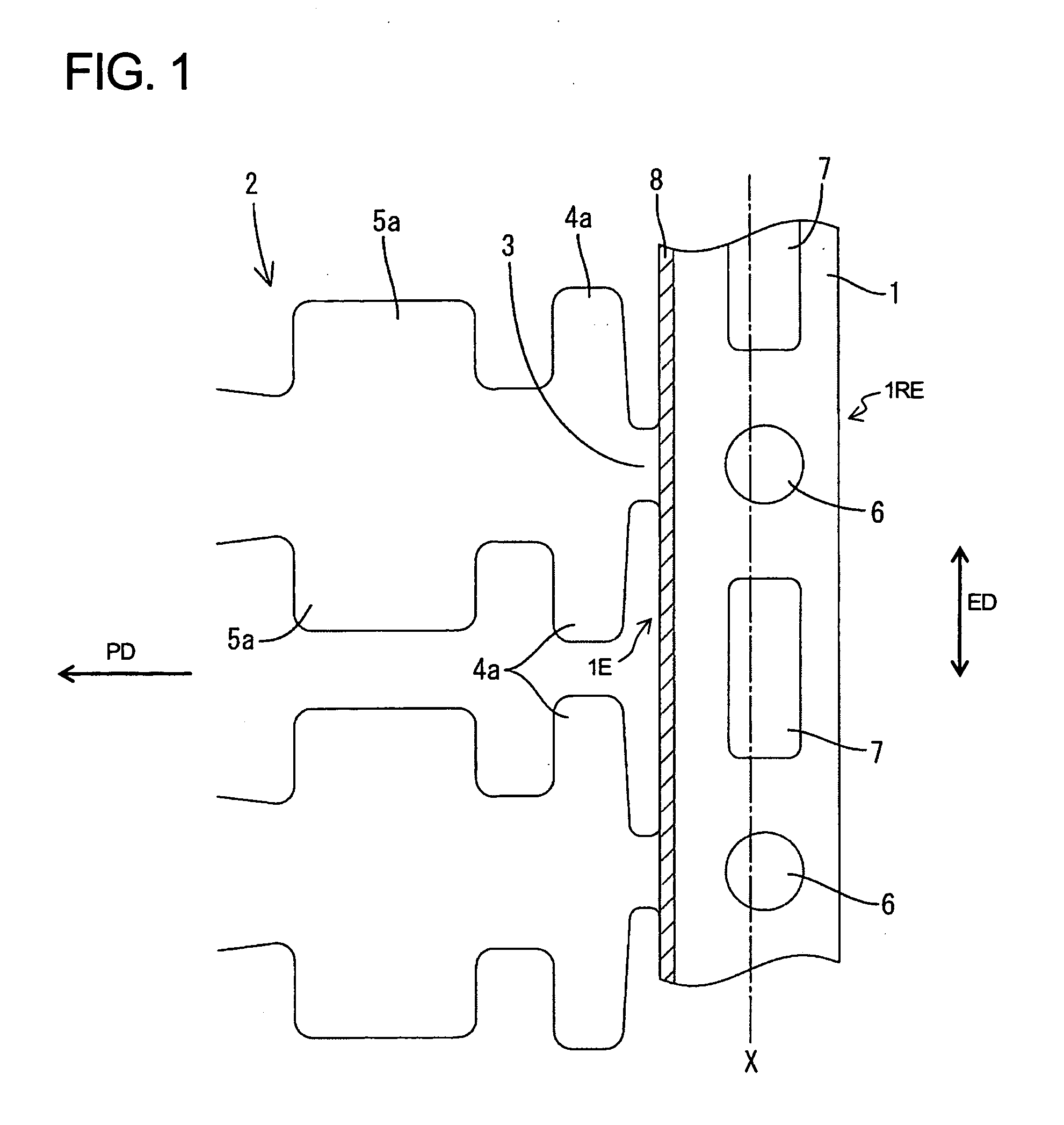
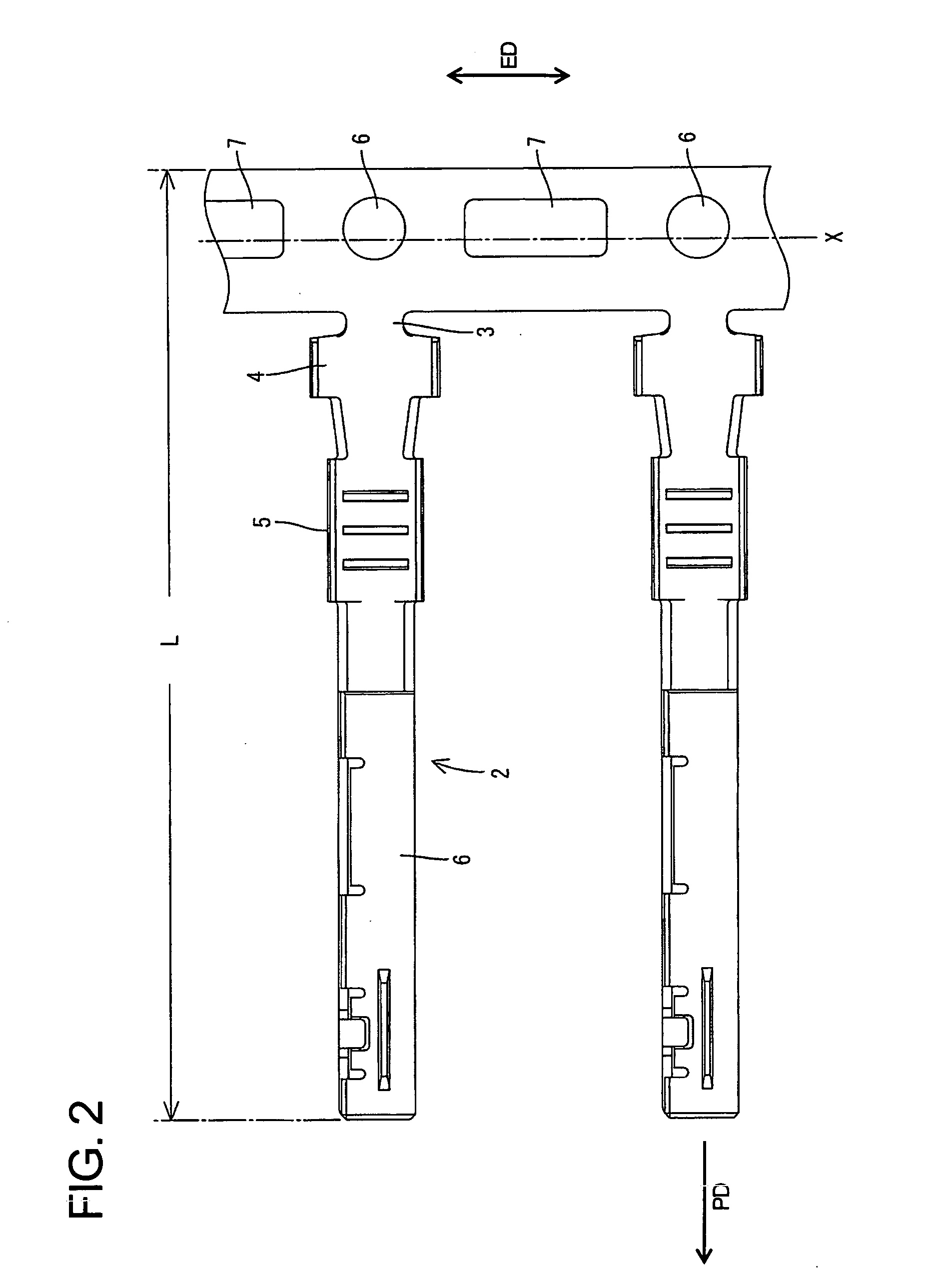
[0023] Chained terminals according to the invention are described with reference to FIGS. 1 and 2. The chained terminals are punched from an elongated metallic plate to define a blank of a specified shape, as shown in FIG. 1. The chained terminals include a carrier 1 in the form of an elongated band that extends in an extending direction ED. The carrier 1 has opposite first and second side edges 1E and 1RE. Female terminal fittings 2 cantilever or project in a projecting direction PD from the first side edge 1E of the carrier 1. The projecting direction PD of each terminal fitting 2 is substantially orthogonal to the extending direction ED of the carrier 1. The terminal fittings 2 are spaced apart at substantially even intervals along the extending direction ED. Coupling pieces 3 extend unitarily between the carrier 1 and the respective terminal fittings 2. The coupling pieces 3 are located substantially on the widthwise center axes of the corresponding terminal fittings 2, as shown...
second embodiment
[0028] The widening of the second embodiment is achieved by reinforcing tabs 8a only in a longitudinal intermediate part of each die-punched region 9 and substantially in the same length range as the second feed hole 7. Thus, an opening of a relatively large width exists between remaining parts of the carrier 1 and the narrower barrel pieces 4a, as shown in FIG. 3.
[0029] The reinforcing tabs 8a of the second embodiment are only in the part of the die-punched region 9 aligned with the second feed holes 7. Thus, a larger stronger press die can be used to form the die-punched region 9, and the carrier 1 is stronger near the second feed holes 7.
[0030] The other construction is similar to the first embodiment, and the first and second feed holes 6, 7 are deviated to the right in FIG. 3 from the widthwise center axis X of the carrier 1, including the widened portions 8a.
[0031]FIG. 4 shows a third embodiment that is similar to the second embodiment. However, the third embodiment has slop...
PUM
| Property | Measurement | Unit |
|---|---|---|
| Length | aaaaa | aaaaa |
Abstract
Description
Claims
Application Information
 - R&D
- Intellectual Property
- Life Sciences
- Materials
- Tech Scout
- Unparalleled Data Quality
- Higher Quality Content
- 60% Fewer Hallucinations
Browse by: Latest US Patents, China's latest patents, Technical Efficacy Thesaurus, Application Domain, Technology Topic, Popular Technical Reports.
© 2025 PatSnap. All rights reserved.Legal|Privacy policy|Modern Slavery Act Transparency Statement|Sitemap|About US| Contact US: help@patsnap.com


