Large-current magnetic latching relay, movable contact spring of large-current magnetic latching relay, and contact assembly of large-current magnetic latching relay

A technology of magnetic latching relays and contact components, applied in electromagnetic relays, electromagnetic relay details, relays, etc., can solve the problem of affecting the accuracy of smart meter detection values, no improvement in the withstand voltage performance of the medium between contacts, and limiting the gap between dynamic and static contacts To achieve the effect of improving the product withstand voltage range, improving the stability of the action, and reducing the formation of arcs

Active Publication Date: 2014-10-08
XIAMEN HONGFA ELECTRIC POWER CONTROLS
View PDF5 Cites 12 Cited by
  • Summary
  • Abstract
  • Description
  • Claims
  • Application Information

AI Technical Summary

Problems solved by technology

[0008] like figure 2 As shown, in the existing double-contact contact system, the current passes through the first lead-out piece 61, two static contacts 62, two moving contacts 64, the moving reed 65 and the second lead-out piece 63 in sequence, and the current is at A large loop will be formed inside the relay, and because of the double contact structure, there will be current shunt, which will form a large range of interference electromagnetic field in the relay, which will affect the adjacent precision circuit components, such as When the magnetic latching relay is used in a smart meter, the induced current generated by the interference electromagnetic field will directly affect the accuracy of the smart meter's detection value
[0009] In addition, in addition to improving the load capacity of the product, this traditional double-contact mode does not improve the contact gap and the withstand voltage performance of the medium between the contacts.
At the same time, the moving reed is arranged between the two lead-out pieces, and the swing range is greatly limited, which also limits the gap between the moving and static contacts.

Method used


Image

  • Large-current magnetic latching relay, movable contact spring of large-current magnetic latching relay, and contact assembly of large-current magnetic latching relay
  • Large-current magnetic latching relay, movable contact spring of large-current magnetic latching relay, and contact assembly of large-current magnetic latching relay
  • Large-current magnetic latching relay, movable contact spring of large-current magnetic latching relay, and contact assembly of large-current magnetic latching relay

Examples


Embodiment Construction

[0044] Typical embodiments embodying the features and advantages of the present invention will be described in detail in the following description. It should be understood that the invention is capable of various changes in different embodiments without departing from the scope of the invention, and that the description and illustrations therein are illustrative in nature and not limiting. this invention.

[0045] The orientations such as up, down, top, and bottom mentioned in the present invention are only used to illustrate the relative positional relationship between the components, and do not limit the specific installation orientations of the components in the present invention.

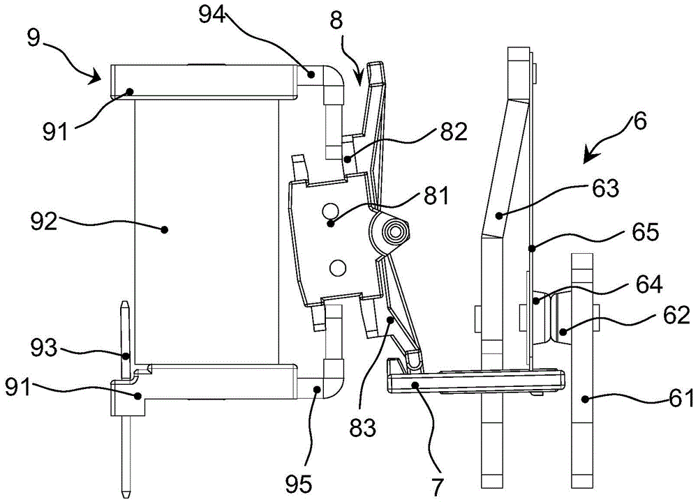
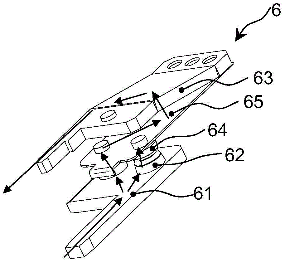
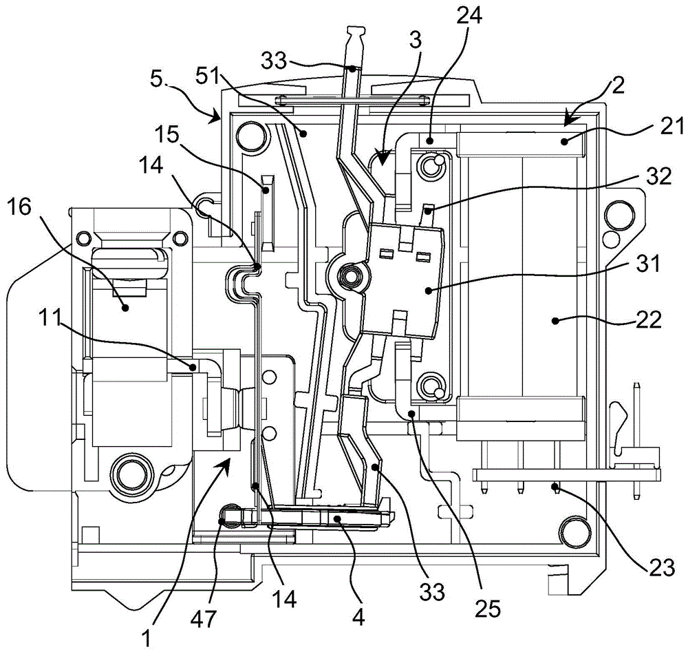
[0046] An embodiment of the present invention provides a large current magnetic latching relay, referring to image 3 , Figure 4 and Figure 5 , The relay mainly includes a contact assembly 1, an electromagnetic assembly 2, an armature assembly 3 and a push card 4, and these components are i...


PUM


Abstract

The invention provides a large-current magnetic latching relay, a movable contact spring of the large-current magnetic latching relay, and a contact assembly of the large-current magnetic latching relay. The large-current magnetic latching relay comprises the contact assembly, an electromagnetic assembly, an armature assembly and a pushing clamp, and under the magnetic attraction action of permanent magnet steel inside the armature assembly, the contact assembly keeps in the normally open state or in the normally closed state; the contact assembly is triggered by pulse electric signals to be switched between the normally open state and the normally closed state, so that the electromagnetic assembly drives the armature assembly to drive the pushing clamp to shift, and the contact assembly is switched between the normally open state and the normally closed state through shifting of the pushing clamp. The movable contact spring of the large-current magnetic latching relay is made of elastic conductive materials and is fixedly provided with at least two movable contacts, the movable contact spring is provided with a fixed first end portion and a second end portion capable of elastically swinging, the movable contacts are fixed to the second end portion and are electrically connected through the movable contact spring, and the second end portion of the movable contact spring is driven by the pushing clamp to swing.

Description

technical field [0001] The invention relates to a high-current magnetic latching relay, in particular to a brand-new high-current magnetic latching relay with a double-contact structure and its moving reed and contact assembly. Background technique [0002] The magnetic latching relay is a new type of relay developed in recent years, and it is an automatic switch. The traditional electromagnetic relay only plays the role of automatically turning on and off the circuit, while the normally open or normally closed state of the magnetic latching relay is completely dependent on the permanent magnet, and the switching state of the relay is triggered by a pulse electric signal with a certain width. Finish. When the contacts of the relay need to be in the open or closed state (that is, when the load is turned on or off), only the positive and negative pulse voltages are used to excite the coil, and the relay completes the switching between the open and closed states in an instant....

Claims


Application Information

Patent Timeline
Patent Type & Authority Applications(China)
IPC IPC(8): H01H50/54H01H51/01
Inventor 郭顺可钟叔明饶丽斌
Owner XIAMEN HONGFA ELECTRIC POWER CONTROLS
Why Eureka
Try Eureka