Method for positioning a welding robot tool

a welding robot and tool technology, applied in the direction of electrical programme control, instruments, program control, etc., can solve the problems of inaccurate positioning of sheets, deterioration of surface quality of finished products, and sheet deformation, so as to reduce operating costs, improve balancing, and reduce investment

Active Publication Date: 2006-09-21
ABB (SCHWEIZ) AG
View PDF21 Cites 63 Cited by
  • Summary
  • Abstract
  • Description
  • Claims
  • Application Information

AI Technical Summary

Benefits of technology

[0024] Another advantage of the invention is that, since the robot itself compensates for the fact that the tool is off centre, lower investments are required and the operating cost is reduced compared with the case whe

Problems solved by technology

Usually, the position of the second fixed arm deviates from the plane of the sheets, which results in the welding causing a deformation of the sheets.
This may lead to deteriorated surface quality on the finished product.
The reasons for the electrode arms not being centred are, for example, that the sheet is not accurately positioned in the fixture that holds the sheet in place, or that the tip of the welding electrodes has been worn down during the course of the welding.
The corresponding problems arise also for other types of joining methods, such a

Method used


Image

  • Method for positioning a welding robot tool
  • Method for positioning a welding robot tool
  • Method for positioning a welding robot tool

Examples


Embodiment Construction

[0030] The following description relates both to the method and to the device.

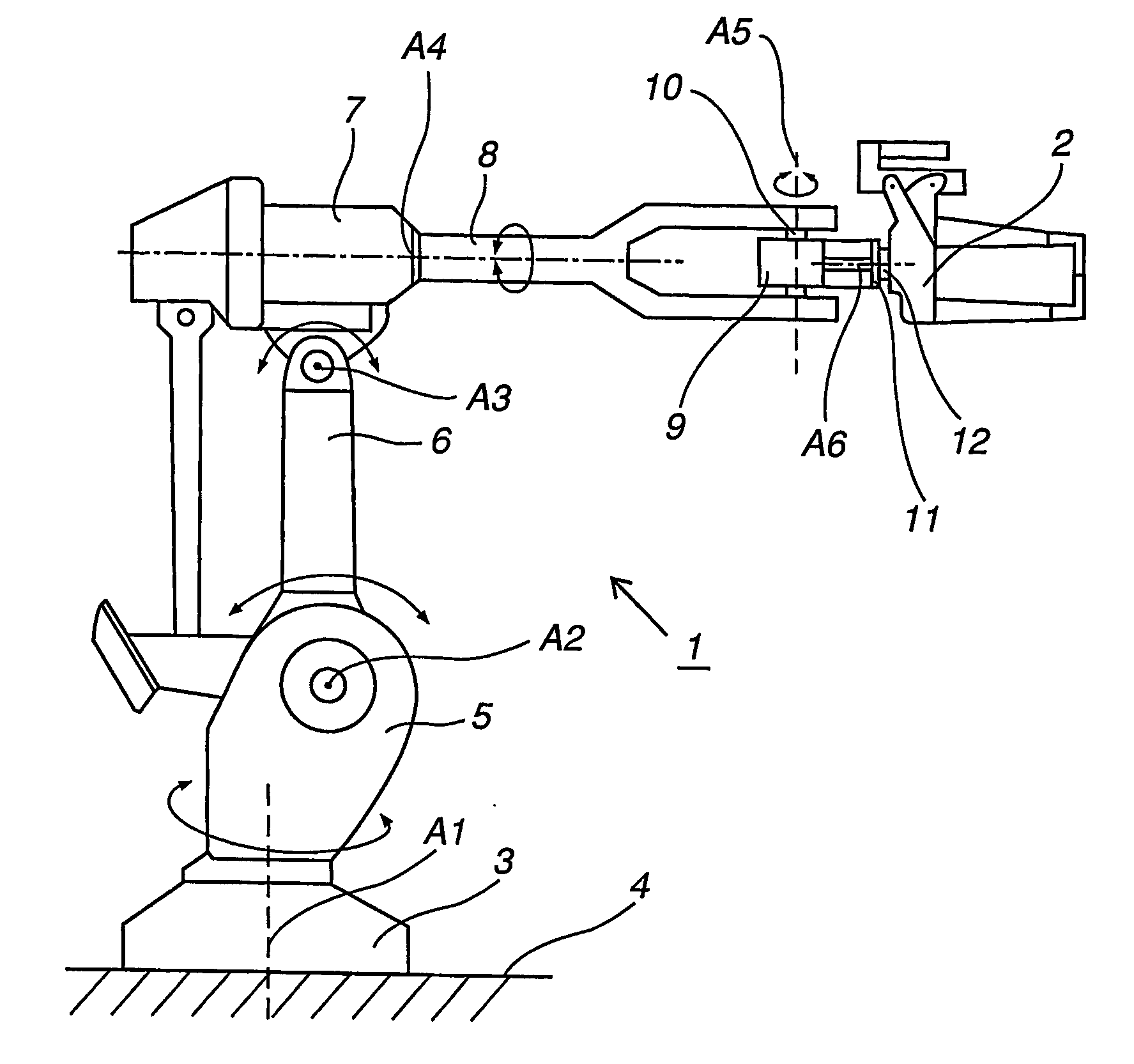
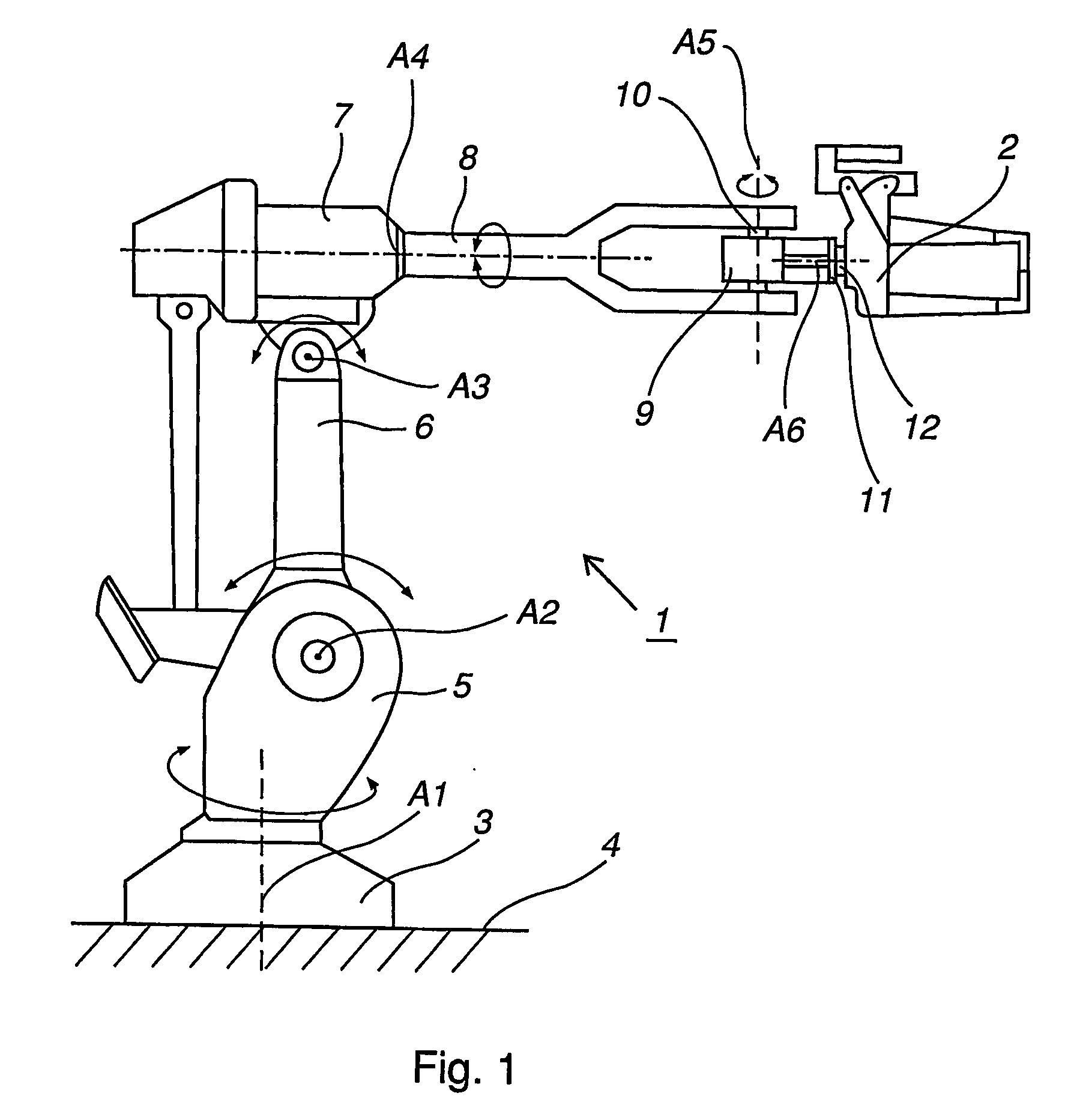
[0031]FIG. 1 shows an example of a prior art industrial robot 1 comprising a tool, a so-called welding gun 2. The industrial robot comprises a foot 3 that is mounted to a base 4. The foot 3 supports a stand 5, which is rotatably arranged in relation to the foot 3 about a first axis A1. The stand 5 supports a first robot arm 6, which is rotatable in relation to the stand 5 about a second axis A2. The first robot arm supports an arm housing 7, which is rotatable in relation to the first robot arm 5 about a third axis A3. The arm housing 7 supports a second robot arm 8, which is rotatable in relation to the arm housing 7 about a fourth axis A4, and where the fourth axis A4 coincides with the longitudinal axis of the second robot arm 8. The second robot arm 8 comprises a wrist housing 9, which is supported by a wrist 10. The wrist housing 9 is rotatable about a fifth axis A5 which coincides with the longitudi...


PUM

PropertyMeasurementUnit
Currentaaaaaaaaaa
Distanceaaaaaaaaaa

Abstract

A method for joining together at least two sheets with a tool controlled by an industrial robot and including a first arm and a second arm that are mutually movable in relation to each other. An actual position of the sheets is detected by bringing one of the arms to sense the actual position of the sheets. The distance between an ideal position and the actual position is calculated and the actual position of the tool is moved the calculated distance, whereafter the sheets are joined together.

Description

TECHNICAL FIELD [0001] The present invention relates to method for joining together at least two sheets by means of a tool controlled by an industrial robot and comprising a first arm and a second arm. BACKGROUND ART [0002] A robot system comprises an industrial robot comprising a manipulator and a control system. The manipulator comprises a robot arm with a wrist housing comprising a turn disc which is rotatably arranged relative to the wrist housing. The turn disc comprises a toolholder which is adapted for attachment of, for example, a tool for joining together at least two sheets by the influence of force and at one point. Examples of such methods of joining are spot welding, riveting and clinching. The control system comprises at least one program module and a plurality of processors which are adapted to attend to the movements of the manipulator based on instructions in a computer program. The turn disc may also be adapted for attachment of a fixture intended to hold at least ...

Claims


Application Information

Patent Timeline
IPC IPC(8): G06F19/00B23K11/31B23Q15/22
CPCB23K11/314B23Q15/22G05B2219/36503G05B2219/45104G05B2219/50049G05B2219/50137
Inventor LUTHARDT, COLIN
Owner ABB (SCHWEIZ) AG
Why Eureka
Try Eureka