
Clutch control apparatus and method

a technology of clutch control and control apparatus, which is applied in the direction of gearing, instruments, tractors, etc., can solve the problems of difficult to smoothly shift the control modes, adversely affect the driving feeling of vehicle operation, and the amount of slip is not directly controlled as desired, so as to enhance the controllability of the clutch

Inactive Publication Date: 2006-09-21
JATCO LTD
View PDF8 Cites 18 Cited by
  • Summary
  • Abstract
  • Description
  • Claims
  • Application Information

AI Technical Summary

Benefits of technology

[0005] On the other hand, in recent years, there is proposed a technique of controlling the engagement pressure to be identical to an actually required engagement pressure, during conditions where the clutch is conventionally fully engaged. That is, during vehicle steady-state driving, the clutch is automatically controlled to balance the clutch capacity with a torque input from the driving side, so that a slip state infinitely close to the fully engaged state (or an engaged state infinitely close to a slip state) is formed. The above technique of avoiding full engagement of the clutch during vehicle starting intends to realize a condition where static frictional force is not acting between the driving and driven sides with the clutch being in the engaged state, to enhance controllability of the clutch with securing the efficiency of torque transmission.
[0007] Accordingly, it is an object of the present invention to provide a clutch control apparatus and a clutch control method to enhance controllability of a clutch in a process including a shift between a slip control mode and a steady-state control mode based on an input torque.

Problems solved by technology

However, if the control mode of the above-mentioned conventional technique based on full engagement of clutch is followed by a mode of called a clutch slip control where the torque capacity is controlled and the amount of slip between the driving and driven sides is controlled and held at a predetermined speed during vehicle starting, it is difficult to smoothly shift the control modes, so that it is possible that a torque shock occurs to adversely affect driving feeling of vehicle operation.
In addition, in the conventional torque capacity control, the clutch torque capacity is set in accordance with the clutch speed ratio, it is possible that the amount of slip is not directly controlled as desired.
Thus, it is possible that the conventional torque capacity control technique cannot control the amount of slip of a clutch arbitrarily in accordance with the clutch torque capacity.

Method used


Image

  • Clutch control apparatus and method
  • Clutch control apparatus and method
  • Clutch control apparatus and method

Examples


Embodiment Construction

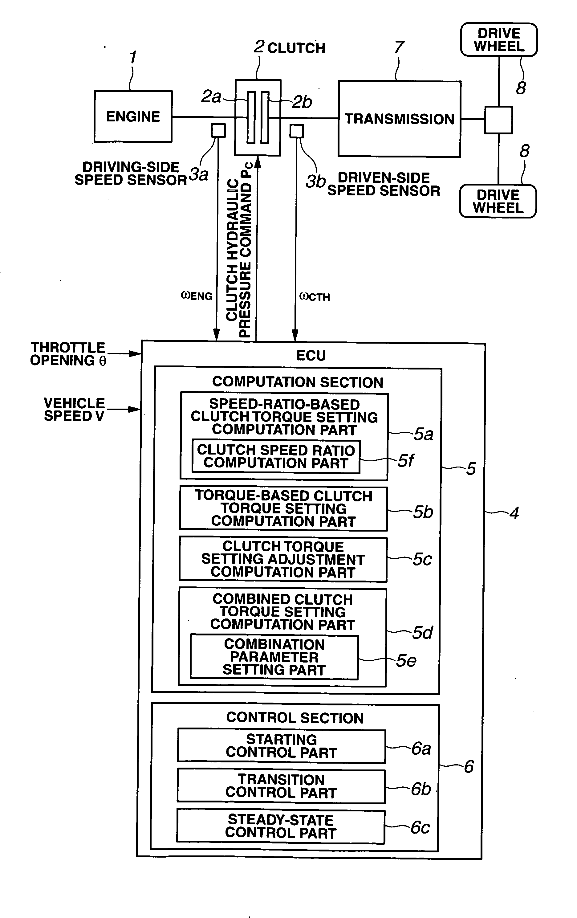
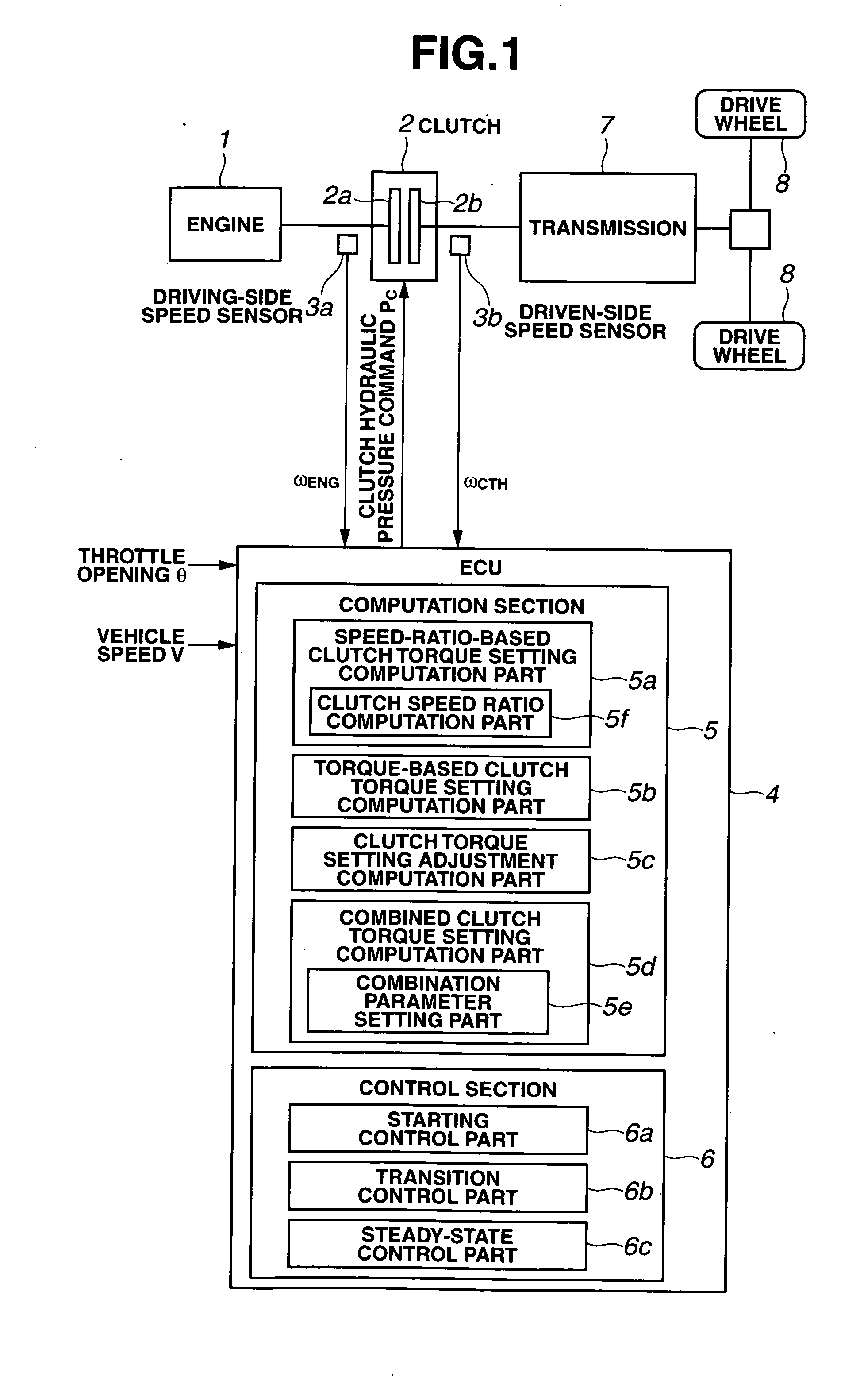
[0016] Referring now to FIG. 1, there is shown a configuration of a clutch control apparatus in accordance with an embodiment of the present invention. FIG. 1 is a schematic block diagram showing a power transmission system of an automotive vehicle with a clutch control apparatus in accordance with an embodiment of the present invention. In this power transmission system, a driving torque output from an engine 1 is transmitted to drive wheels 8, 8 via a transmission 7. On the driveline connecting engine 1 and drive wheels 8, 8, specifically, between engine 1 and transmission 7, a multiplate wet clutch 2 is provided as a friction clutch. Clutch 2 includes a driving engaging member 2a such as a driving clutch plate arranged to rotate by the driving torque of engine 1, and a driven engaging member 2b such as a driven clutch plate disposed in parallel to driving engaging member 2a. Specifically, clutch 2 includes a friction clutch adapted to couple the input rotating member and the outp...


PUM


Abstract

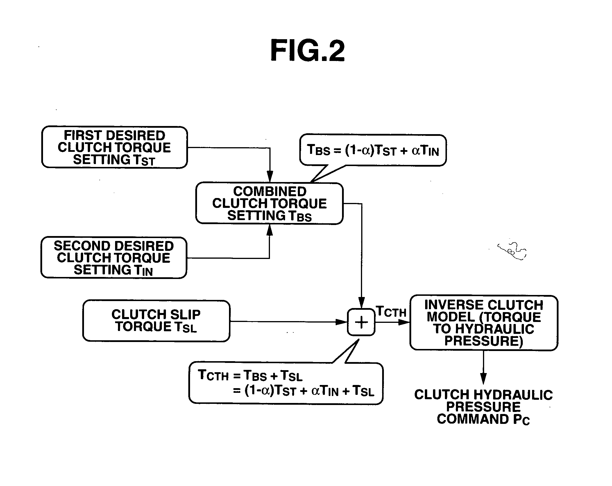
A clutch control apparatus for a power transmission system including an input rotating member and an output rotating member. The clutch control apparatus includes a friction clutch, and a control unit. The control unit sets a first desired clutch torque setting in accordance with a clutch slip indicator; sets a second desired clutch torque setting to an amount of torque input from the input rotating member to the friction clutch; controls the clutch torque to be the first desired clutch torque setting during a starting stage of the friction clutch; controls the clutch torque to be the second desired clutch torque setting during a steady-state stage of the friction clutch; and controls the clutch torque to gradually change from the first desired clutch torque setting to the second desired clutch torque setting during a transition stage between the starting stage and the steady-state stage.

Description

BACKGROUND OF THE INVENTION [0001] The present invention relates to clutch control apparatus and method for controlling a torque transmitted between an input rotating member and an output rotating member of a power transmission system. [0002] Conventionally, there is known a clutch control technique for automotive vehicle, which controls the magnitude of a torque transmitted from an engine to a drive wheel by automatically engaging and disengaging a clutch during vehicle starting or running. A Published Japanese Patent Application No. H9-72353 (hereinafter referred to as “JP9-72353”) shows a clutch control technique that derives a clutch torque capacity coefficient in accordance with a clutch speed ratio defined as a ratio of the rotational speed of a driven-side rotating member to the rotational speed of a driving-side rotating member, using a predetermined map defining a relationship between the clutch speed ratio and the clutch torque capacity coefficient, computes a desired torq...

Claims


Application Information

Patent Timeline
IPC IPC(8): G06F17/00F16D48/02F16H59/14F16H59/24F16H59/40F16H59/42F16H59/44F16H59/46F16H59/56F16H61/02
CPCF16D48/06F16D2500/1026F16D2500/30406F16D2500/50224Y10T477/755F16D2500/7044Y10T477/753Y10T477/6203Y10T477/638F16D2500/70426F16D13/00B60K17/00F16H3/00F16D25/14
Inventor HONMA, TOMOAKIUCHIDA, MASAAKIKATAKURA, SHUSAKUKAWAMOTO, YOSHINOBU
Owner JATCO LTD
Learn More