Micro-machined pressure sensor with polymer diaphragm

a pressure sensor and polymer diaphragm technology, applied in the field of micro-machined sensors, can solve the problems of relatively large sensors, relatively low resistivity of piezoresistive metals, and low gauge factors of metal foils, and achieve the effect of modulating the electrical conductivity of the piezoresistive region

Active Publication Date: 2006-09-28
HONEYWELL INT INC
View PDF13 Cites 42 Cited by
  • Summary
  • Abstract
  • Description
  • Claims
  • Application Information

AI Technical Summary

Benefits of technology

[0004] The following summary of the invention is provided to facilitate an understanding of some of the innovative features unique to the present invention and is not intended to be a full description. A full appreciation of the invention can be gained by taking the entire specification, claims, drawings, and abstract as a whole.
[0005] The present invention relates generally to micro-machined sensors such as pressure and / or strain sensors, and more particularly to micro-machined primarily plastic and / or glass piezoresistive sensors. In one illustrative embodiment, a piezoresistive pressure sensor is formed on a polymer substrate. A first selectively ion implanted region is provided in the polymer substrate to create a piezoresistive region in the polymer substrate. A second selectively implanted region is then provided in at least part of the first selectively ion implanted region to modulate the electrical conductivity of the first selectively implanted region. The illustrative sensor may be selectively implanted with, for example, nitrogen to create the piezoresistive region, and boron to modulate the electrical conductivity of the piezoresistive region. Phosphorus or any other suitable chemical element or material may also be used to modulate the electrical conductivity of the piezoresistive region, as desired.

Problems solved by technology
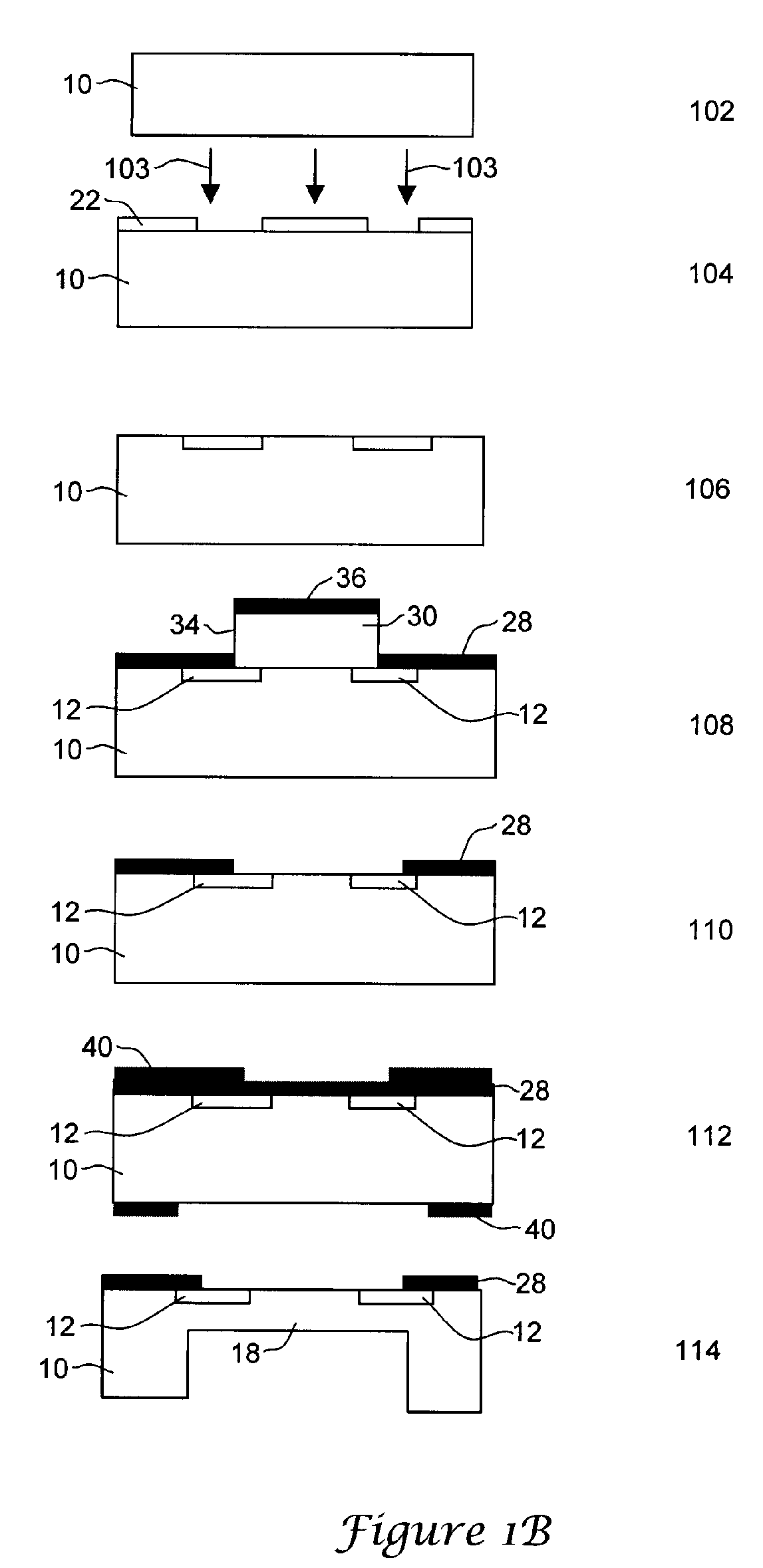
Some drawbacks of these types of sensors include the de-lamination of the metal film over time, the relatively low resistivity of the piezoresistive metal, thereby requiring relatively large sensors, and rather low gauge factors for the metal foils.
In spite of the well-established silicon MEMS technology, the cost of these devices cannot usually be reduced below certain limits, often due in part to the cost of the single crystal silicon substrate.

Method used


Image

  • Micro-machined pressure sensor with polymer diaphragm
  • Micro-machined pressure sensor with polymer diaphragm
  • Micro-machined pressure sensor with polymer diaphragm

Examples


Embodiment Construction

[0014] The following description should be read with reference to the drawings wherein like reference numerals indicate like elements throughout the several views. The detailed description and drawings show several embodiments, which are meant to be illustrative of the claimed invention

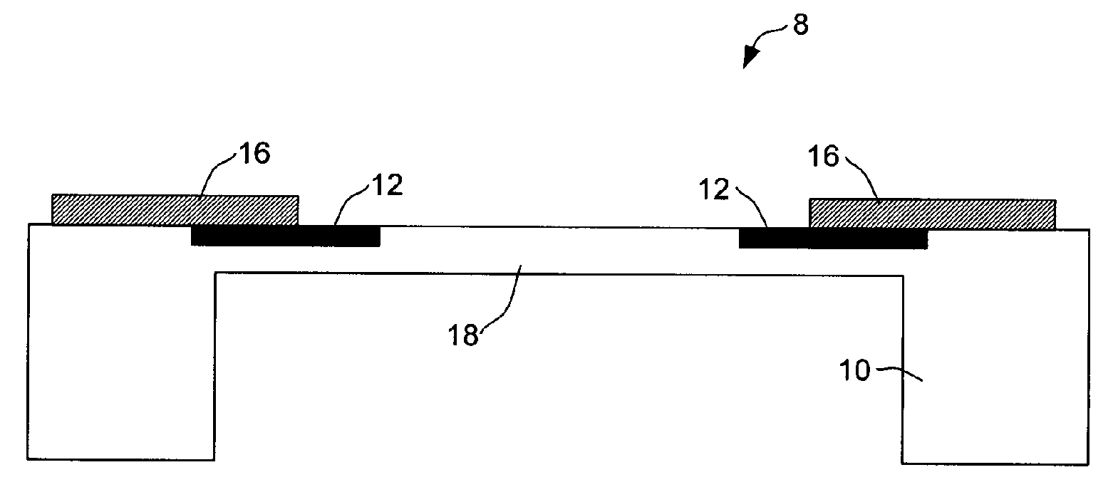
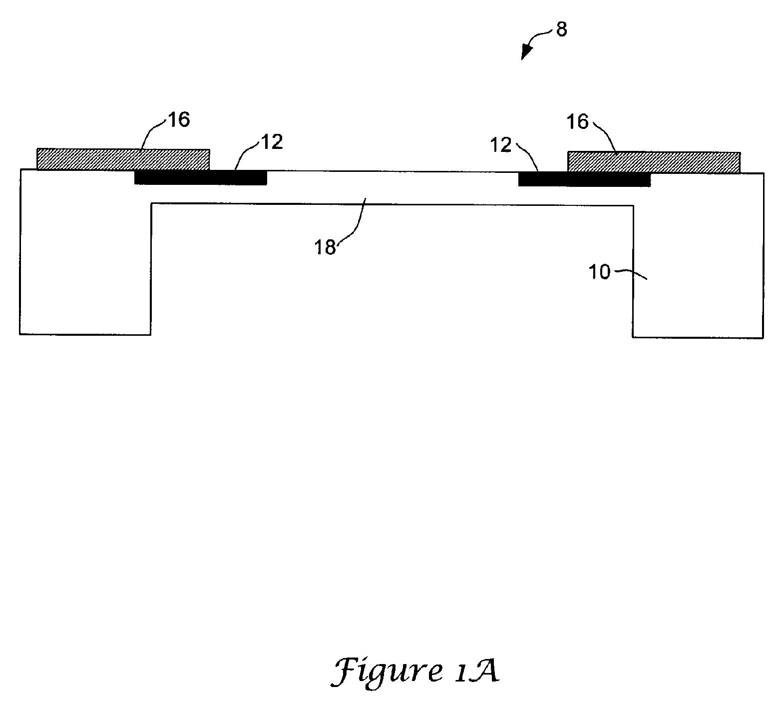
[0015]FIG. 1A is a schematic cross-sectional side view of an illustrative piezoresistive pressure sensor in accordance with the present invention. While a pressure sensor is shown, it is contemplated that the present invention may be applied to other types of sensors, such as strain gauges, etc. The illustrative piezoresistive pressure sensor may be an absolute pressure sensor or a differential pressure sensor, as desired. In some cases, the pressure sensor may be a substantially all-plastic pressure sensor with implanted piezoresistive regions.

[0016] In FIG. 1A, the pressure sensor is generally shown at 8 and includes a polymer substrate 10. In some cases, the polymer substrate 10 may be a plastic ...


PUM

PropertyMeasurementUnit
thicknessaaaaaaaaaa
thicknessaaaaaaaaaa
thicknessaaaaaaaaaa

Abstract

A piezoresistive pressure and/or strain sensor micro-machined primarily from plastic and/or glass. In one illustrative embodiment, the piezoresistive pressure sensor is formed on a polymer substrate. A first selectively implanted region is provided in the polymer substrate to create a piezoresistive region in the polymer substrate. A second selectively implanted region is then provided in at least part of the first selectively implanted region to modulate the electrical conductivity of the first selectively implanted region. The illustrative sensor may be selectively implanted with, for example, nitrogen to create the piezoresistive region, and boron to modulate the electrical conductivity of the piezoresistive region. Phosphorus or any other suitable material may also be used to modulate the electrical conductivity of the piezoresistive region, as desired. The piezoresistive pressure/strain sensor may be formed from a single substrate, or two or more substrates, and the resulting pressure/strain sensor may be mounted in a plastic package, if desired.

Description

FIELD [0001] The present invention relates generally to micro-machined sensors and more particularly to micro-machined plastic piezoresistive pressure and / or strain sensors. BACKGROUND [0002] There is a need for new low cost sensors, such as strain and / or pressure sensors. One application for such low cost sensors is in the disposable market, such as in the biomedical domain where single use devices are often used. Many other markets and applications also exist. In the past decade, there has been progress made in the development of polymer thin and thick films for use as flexible electronics and different sensing applications. For example, piezoresistive metal foils have been deposited on flexible polymer substrates to form strain gauges. Some drawbacks of these types of sensors include the de-lamination of the metal film over time, the relatively low resistivity of the piezoresistive metal, thereby requiring relatively large sensors, and rather low gauge factors for the metal foils...

Claims


Application Information

Patent Timeline
Patent Type & Authority Applications(United States)
IPC IPC(8): G01L9/00
CPCG01L1/18G01L1/2287G01L9/0052
Inventor COBIANU, CORNEL P.GOLOGANU, MIHAIPAVELESCU, IOANSERBAN, BOGDAN CATALIN
Owner HONEYWELL INT INC
Why Eureka
Try Eureka