
Lash adjustment for piston rollers

a piston roller and lash adjustment technology, applied in the direction of gearing elements, positive displacement engines, gearing, etc., can solve the problems of complex adjustment of such lash, unsatisfactory slippage and differential wear,

Inactive Publication Date: 2006-09-28
THOMAS C RUSSELL
View PDF1 Cites 14 Cited by
  • Summary
  • Abstract
  • Description
  • Claims
  • Application Information

AI Technical Summary

Benefits of technology

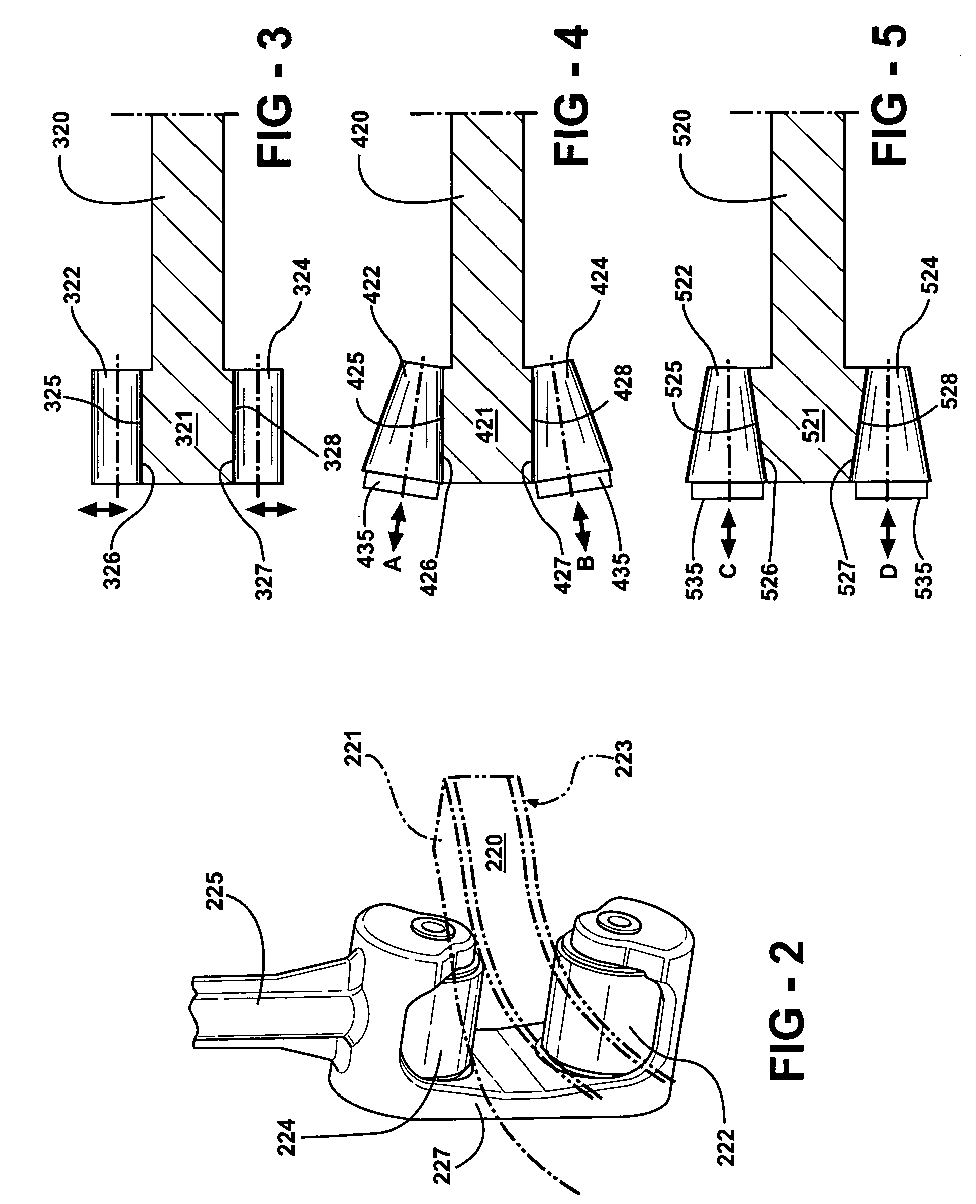
[0022] Other embodiments of an inventive method include applying force to a second roller, moving the second roller towards the inner side of the cam plate, where the provided system further comprises a second roller in mechanical communication with the second surface of a cam plate track portion to allow rotational engagement of a roller surface of the second roller with the second surface of the cam plate track portion, the second roller having a rotational axis and a frustoconical shape, and force applying means for moving the second roller towards the inner side of the cam plate, such that lash between the second roller and the second surface of the cam plate is reduced.

Problems solved by technology

Inner and outer portions of the rollers may rotate at different speeds following around the cam plate, resulting in lash causing undesirable slippage and differential wear.
Adjustment of such lash is complex and time consuming.

Method used


Image

  • Lash adjustment for piston rollers
  • Lash adjustment for piston rollers
  • Lash adjustment for piston rollers

Examples


Embodiment Construction

[0033] This application is related to engines that include rollers that roll along a surface, such as shown in Applicant's co-pending patent application Ser. No. 10 / 791,453, the entire content of which is incorporated herein by reference. As discussed in that, and other of Applicant's applications and patents, engines such as barrel engines may include a cam plate with an oscillating track in mechanical communication with pistons so that as the plate rotates, the pistons reciprocate within their cylinders. Communication between the surface of the cam plate and the pistons requires some type of sliding or roller mechanism. The present application is directed towards rollers for providing such a communication, and lash adjustment for those rollers.

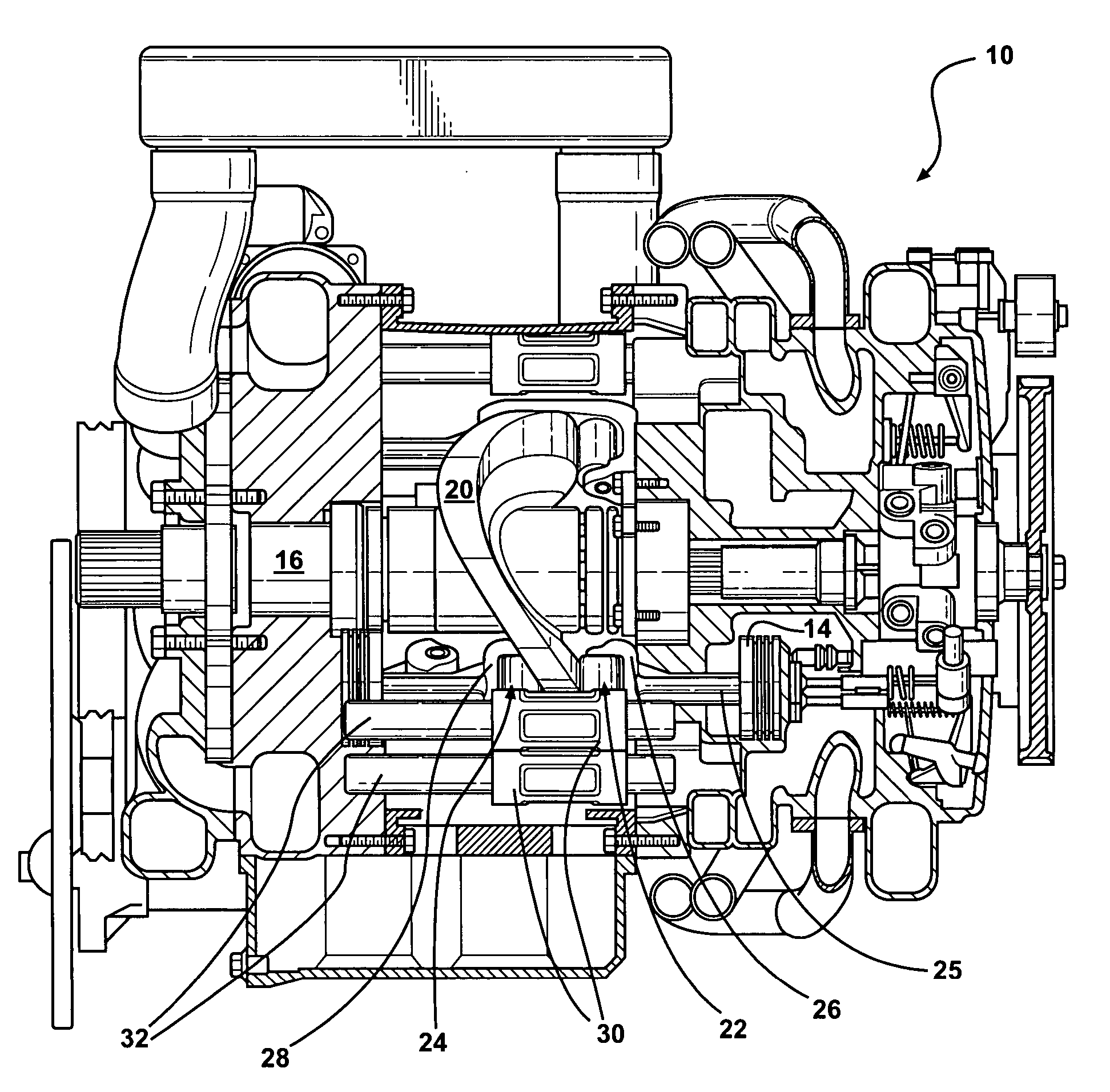
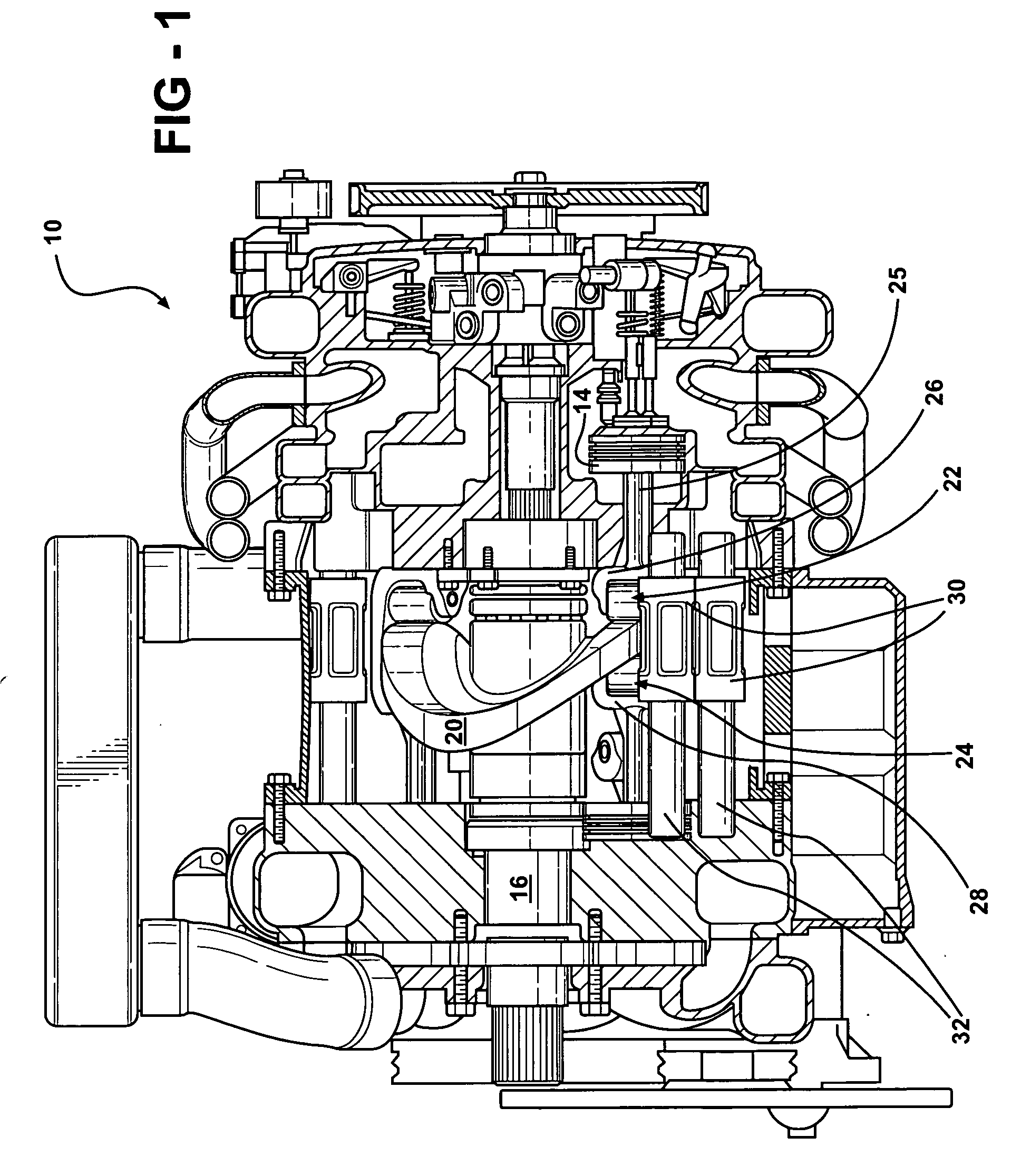
[0034]FIG. 1 shows a barrel type internal combustion engine 10 which includes a plurality of pistons 14 arranged concentrically about a central driveshaft assembly 16. Power is transmitted from the pistons 14 to a cam plate 20 via a roller ...


PUM


Abstract

A lash adjustment system for a roller is provided which includes a cam plate surface and a frustoconically shaped roller in mechanical communication with the surface. Means for moving the roller relative to the surface are included to urge the roller inwardly with respect to the cam plate in order to reduce lash.

Description

REFERENCE TO RELATED APPLICATION [0001] This application claims priority of U.S. Provisional Patent Application Ser. No. 60 / 656,017, filed Feb. 24, 2005, the entire content of which is incorporated herein by reference.FIELD OF THE INVENTION [0002] The present invention generally relates to engines that include one or more rollers that roll along a surface, and more particularly, to methods and apparatus for reduction of lash between such a roller and surface. BACKGROUND OF THE INVENTION [0003] Cam plate barrel engines utilize a drive means that consists of a plate with an undulating cam surface normally capable of reciprocating the pistons through four or more cycles per one revolution of the driveshaft. A piston in a cam plate barrel engine generally communicates with the cam plate via a pair of rolling elements that follow the undulating surface of the cam plate. [0004] In a typical arrangement, a cylindrical rolling element having a generally uniform cross-sectional diameter alon...

Claims


Application Information

Patent Timeline
Patent Type & Authority Applications(United States)
IPC IPC(8): F16H25/08
CPCF01B3/02F02B75/26Y10T74/18304F16H57/12F16H53/06
Inventor THOMAS, C. RUSSELL
Owner THOMAS C RUSSELL
Learn More