Method for orbital welding using a pulsed current

a pulsed current and orbital welding technology, applied in the direction of soldering apparatus, manufacturing tools, auxillary welding devices, etc., can solve the problems of increasing the width increasing the temperature of the adjacent area, increasing the temperature of the weld bead, etc., to achieve the effect of reducing the width and smoothly disengaging

Inactive Publication Date: 2006-09-28
ORBITAL ACQUISITION
View PDF1 Cites 12 Cited by
  • Summary
  • Abstract
  • Description
  • Claims
  • Application Information

AI Technical Summary

Benefits of technology

[0049] This rapid decrease in current after the conclusion of at least one orbit around the tubular components allows for a smooth transition out of a weld. Instead of an abrupt end to the weld, possibly causing weld failure, the weld bead is gradually reduced in width, overlapping the start of the weld, and tapering to point where the arc can be smoothly disengaged.

Problems solved by technology

If the current is not decreased, a surplus of internal energy will accumulate, increasing weld bead and adjacent area temperature to an unacceptable level, causing additional parent material to melt.
The weld bead, as a result, will increases to an unacceptable width in some areas, possibly collapsing or rupturing, while possibly being under penetrated in other areas.
Therefore, if a constant current is applied to an orbital weld, it is likely that the components will overheat, causing the weld bead to be enlarged to an unacceptable point.
One of the primary disadvantages of the single orbit current step reduction method is that it is, quite often, a difficult and time consuming process to program an effective weld schedule for the electronic controlling means of the orbital welding device.
Because, from mere observation, it is not always predictable how exactly the heat generation in any one section relates to a temperature rise in the other sections, it is difficult for the practitioner to calculate which sections need current adjustment in order to effect the geometry of the weld bead in another section.
For example, a current adjustment in one section might be programmed to correct a problematic weld bead geometry in another section observed after a test weld; and the following test weld could reveal that the weld bead in the previously problematic section has been corrected, but the weld bead geometry in another previously unaffected section has been negatively affected by the adjustment.
A welding practitioner may spend many hours repeatedly correcting the weld bead geometry in one section, only to find that the weld bead geometry in another section has been adversely affected.
This long cycle of repetitive correcting becomes even more complicated if the weld schedule is divided in to yet more sections.
Another disadvantage of the current step reduction method is an inconsistent weld bead.
However, increasing the number of current reduction steps significantly complicates the task of programming a suitable weld schedule.
Because the current is constant, there is no way to prevent overheating in these areas of more complete penetration.
It is possible that the resulting weld bead characteristics in the first approximate quadrant are acceptable, but the overheated areas would be characterized by an undesirably large, over-penetrated weld bead.
Because it is a desired result to produce a weld bead with constant penetration and geometrical characteristics, the multiple orbit constant current method is not usually the best option.

Method used


Image

  • Method for orbital welding using a pulsed current
  • Method for orbital welding using a pulsed current
  • Method for orbital welding using a pulsed current

Examples


Embodiment Construction

[0060] The detailed description set forth below in connection with the appended drawings is intended as a description of presently-preferred embodiments of the invention and is not intended to represent the only forms in which the present invention may be constructed and / or utilized. The description sets forth the functions and the sequence of steps for constructing and operating the invention in connection with the illustrated embodiments. However, it is to be understood that the same or equivalent functions and sequences may be accomplished by different embodiments that are also intended to be encompassed within the spirit and scope of the invention.

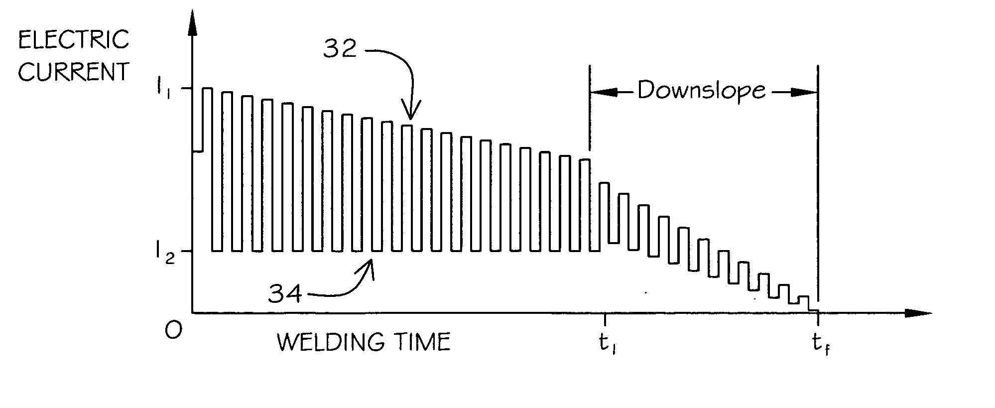
[0061] In accordance with the present invention, a pulsed current adjustment method for orbital welding is provided. The present invention achieves a weld bead structure with desirable constant penetration and geometrical characteristics. Moreover, the method achieves an effective and simple weld schedule, without the need for unneces...


PUM

PropertyMeasurementUnit
currentaaaaaaaaaa
frequencyaaaaaaaaaa
temperatureaaaaaaaaaa

Abstract

A method for the orbital welding of tubular elements held in abutment comprising the steps of striking an arc at a strike point with an orbital welder between an electrode and a seam formed by a first tubular element and a second tubular element, held in abutment within a fixture; initiating an orbit of said electrode around an abutment of said first tubular element and said second tubular element; adjusting the current of said arc in a pulsed manner from a maximum current to a minimum current at a set frequency, combination of said maximum current and said minimum current forming an average current; decreasing said average current in a generally continuous manner as said orbit of said electrode progresses from said strike point, the rate of decrease of said maximum current having a generally inverse relationship to the rate of increase in temperature experienced by said tubular elements.

Description

CROSS-REFERENCE TO RELATED APPLICATIONS [0001] This application is entitled to the benefit of Provisional Application for Patent Ser. No. 60 / 665,410 filed on Mar. 25, 2005.BACKGROUND OF THE INVENTION [0002] This invention relates to a method for welding metal tubes and components. More particularly, the present invention relates to a method of affecting the weld bead geometry by continuously decreasing the average pulsed electric current supplied to an orbital welding device during the welding process, to compensate for the temperature increase experienced in the metal components. [0003] When butt welding together two metal components with tubular extensions, using an orbital welding device, such as the device disclosed in U.S. Pat. No. 5,196,664 to McGushion (1993), it is generally a desired result to create a weld bead which completely penetrates the walls of the tubular extensions, has a weld bead which fully covers the inner diameter and outer diameter seam formed between the tw...

Claims


Application Information

Patent Timeline
Patent Type & Authority Applications(United States)
IPC IPC(8): B23K9/09
CPCB23K9/0286B23K9/092B23K9/093
Inventor MCGUSHION, KEVIN
Owner ORBITAL ACQUISITION
Why Eureka
Try Eureka