Physical quantity distribution detector, physical information acquiring method, and physical information acquiring device

Inactive Publication Date: 2006-09-28
SONY CORP
View PDF6 Cites 48 Cited by
  • Summary
  • Abstract
  • Description
  • Claims
  • Application Information

AI Technical Summary

Benefits of technology

[0059] In applying the count processing to the reference component and the signal component, it is advisable to obtain a count value corresponding respective magnitudes of the reference component and the signal component by pulse-counting a width of a predetermined count object pulse using a signal outputted from the signal converter as a counter clock. It is possible to lower a frequency of a gate signal used for count processing for AD conversion.
[0060] In performing the count processing in the down-count mod

Problems solved by technology

Therefore, output signals are susceptible to influences of a substrate bias effect and a wiring length and are poor in a noise resistance property (a first problem).
Thus, the first problem also occu

Method used


Image

  • Physical quantity distribution detector, physical information acquiring method, and physical information acquiring device
  • Physical quantity distribution detector, physical information acquiring method, and physical information acquiring device
  • Physical quantity distribution detector, physical information acquiring method, and physical information acquiring device

Examples


second embodiment

Schematic Constitution of an Imaging Apparatus; Second Embodiment

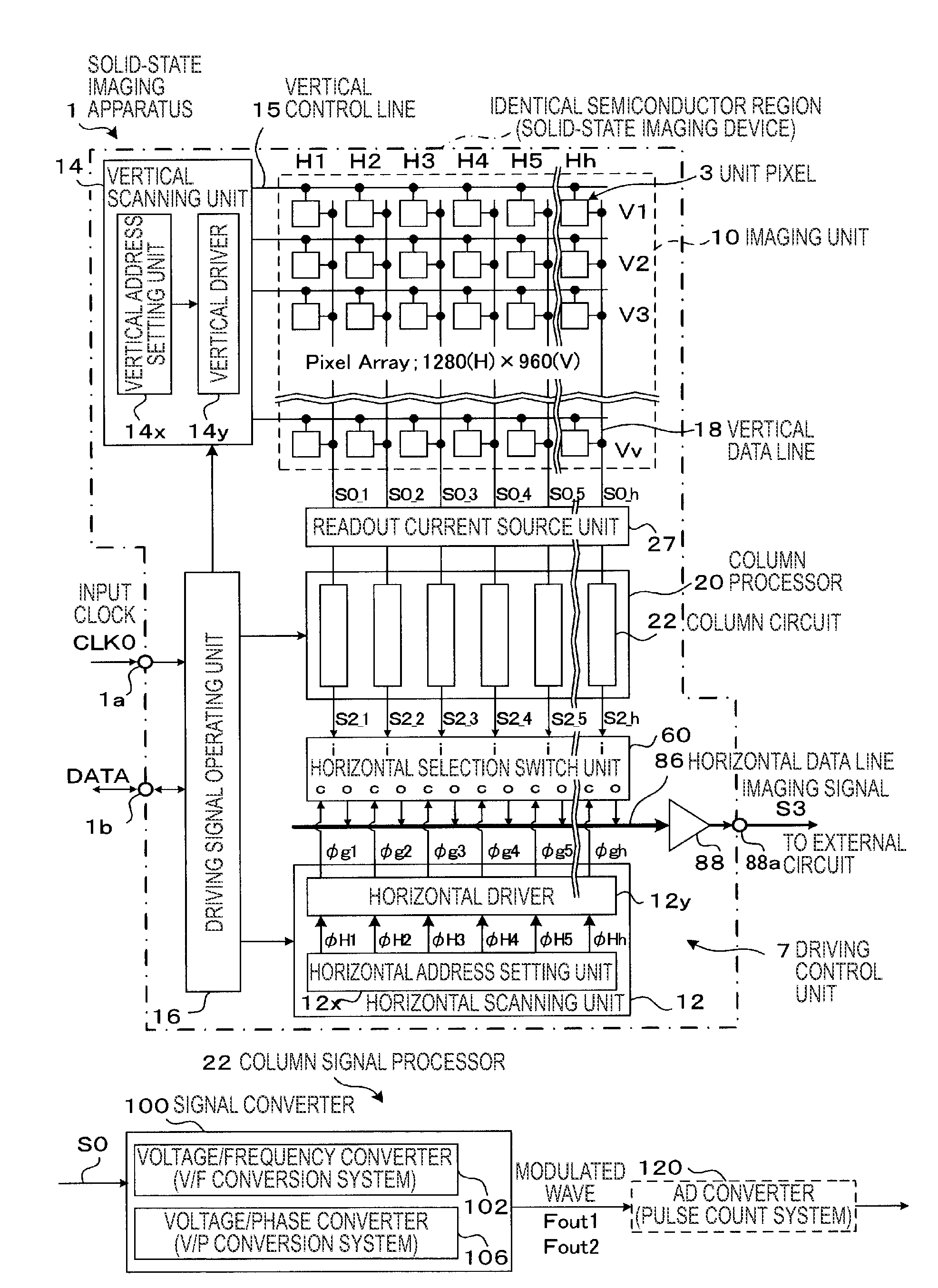
[0198]FIG. 5 is a schematic diagram of a CMOS solid-state imaging device that is a form of a physical information acquiring device according to a second embodiment of the invention. In particular, focusing on the column processor 20, the column processor 20 is shown together with main peripheral units thereof. In the solid-state imaging device 1 in the second embodiment, compared with the solid-state imaging device 1 in the first embodiment, a constitution of the column signal processor 22 (in particular, a post stage circuit of the AD converter 120) is transformed.

[0199] The column signal processor 22 in the second embodiment includes, at a post stage thereof (specifically, a post stage of the pulse count processor 122 or the pulse count processor 128 in FIG. 2; collectively referred to as the count processor 121), a data storing unit 130 serving as an n-bit memory device that holds a count result held by the AD conv...

fifth embodiment

Schematic Constitution of an Imaging Apparatus; Fifth Embodiment

[0252]FIGS. 12A and 12B are diagrams for explaining a CMOS solid-state imaging device that is a form of a physical information acquiring device according to a fifth embodiment of the invention. The fifth embodiment is described as a modification to the first example of the third embodiment. However, it is also possible to apply a modified form explained below to the second example of the third embodiment and the first and the second examples of the fourth embodiment in the same manner.

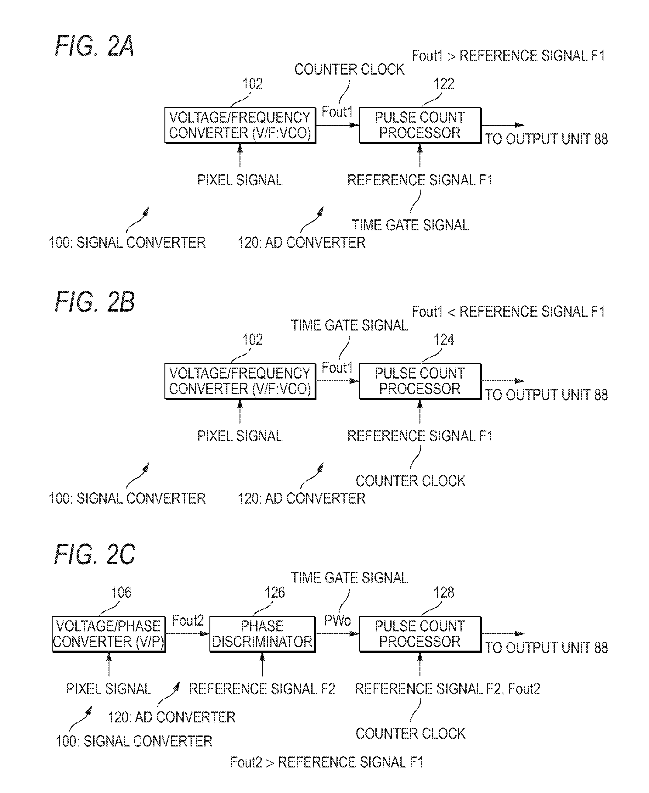
[0253] The fifth embodiment has a characteristic in that a signal converter 101 that directly performs signal conversion by FM modulation or PM modulation on the basis of a signal charge generated by the charge generator 32 is provided. In order to directly perform the FM modulation or the PM modulation, as shown in FIG. 1A, the signal converter 100 only has to be formed as a modulation circuit of a charge injection type. In other words, ...


PUM


Abstract

There is provided a physical information acquiring method of acquiring physical information for a predetermined purpose on the basis of change information that is acquired under predetermined detection conditions for a physical quantity using an portion for physical quantity distribution detection. The portion for physical quantity distribution detection includes a detector that detects change information corresponding to a change in a physical quantity made incident on the detector and has unit components that output unit signals based on the change information detected by the detector arranged in a predetermined order. In the physical information acquiring method, a carrier signal is converted into a signal related to a frequency on the basis of the change information detected by the detector. The physical information for a predetermined purpose is acquired using the signal related to a frequency.

Description

CROSS-REFERENCES TO RELATED APPLICATIONS [0001] This application contains subject matter related to Japanese Patent Application JP 2005-083048 filed in the Japanese Patent Office on Mar. 23, 2005, the entire contents of which being incorporated herein by reference. BACKGROUND OF THE INVENTION [0002] 1. Field of the Invention [0003] The present invention relates to a physical quantity distribution detector, a physical information acquiring method, and a physical information acquiring device. More specifically, the invention relates to a technology for acquiring information for predetermined purposes that is suitable in using a portion for physical quantity distribution detection (a physical quantity distribution detector) such as a solid-state imaging device that has plural unit components, which have sensitivity to electromagnetic waves inputted from the outside such light and radiations, arranged therein and is capable of reading out a physical quantity distribution converted into ...

Claims


Application Information

Patent Timeline
IPC IPC(8): H01L27/00H01L27/146H04N5/32H04N5/335H04N5/357H04N5/369H04N5/374H04N5/378
CPCH01L27/14645H01L27/1464H04N3/1512H04N25/616H04N25/76H04N25/60H04N25/75
Inventor FUKUSHIMA, NORIYUKI
Owner SONY CORP
Why Eureka
Try Eureka