
Method and apparatus for analyzing optical characteristics of optical medium and method for production monitoring

a technology of optical characteristics and analysis methods, applied in the direction of optical radiation measurement, polarisation-affecting properties, instruments, etc., can solve the problems of insufficient description of actual film properties, difficult to express the exact internal micro-structure of an actual optical film, and difficult to precisely express the optical characteristics of the actual optical film by these methods. achieve the effect of stably producing optical media

Active Publication Date: 2006-09-28
FUJIFILM CORP
View PDF3 Cites 10 Cited by
  • Summary
  • Abstract
  • Description
  • Claims
  • Application Information

AI Technical Summary

Benefits of technology

[0007] It is therefore an object of the present invention to provide a method for measuring optical characteristics at, under oblique incidence of light, of an optical medium by obtaining the Jones matrix at an oblique angle of an optical medium capable of polarization conversion, using vectors of light obliquely incident on the optical medium and measured vectors of the output light. It is another object of the present invention to provide a method and an apparatus capable of exactly analyzing the optical characteristics of an optical medium having polarization conversion properties, without using any conventional uniaxial, biaxial and multi-layered models. It is still another object of the present invention to provide a method for stably producing optical mediums exhibiting uniform optical properties.
[0024] According to the present invention, optical characteristics of an optical medium is analyzed by determining the Jones matrix which expresses transformations in polarization state of an obliquely incident light, without using any conventional uniaxial, biaxial or multi-layered model. As a result, the present invention can produce excellent effects of making it possible to more exactly express the optical characteristics of the optical medium, and to more precisely design displays based on characteristics of the actual film. The present invention can also provide a method for production monitoring contributive to improvements in production stability of optical mediums.

Problems solved by technology

It is, however, difficult for these methods to exactly express the optical characteristics of the actual optical films.
Because of complexity of internal structures of the actual optical films (see Y. Takahashi, H. Watanabe, T. Kato: Proc. Jpn. Liq. Cryst. Conf. (2003) p.194, for example), these models, such as a simple uniaxial model or a biaxial model, are insufficient to describe the actual film properties.
It is also difficult to express an exact internal micro-structure of an actual optical film with a multi-layered birefringent media model having an optical axis.

Method used


Image

  • Method and apparatus for analyzing optical characteristics of optical medium and method for production monitoring
  • Method and apparatus for analyzing optical characteristics of optical medium and method for production monitoring
  • Method and apparatus for analyzing optical characteristics of optical medium and method for production monitoring

Examples


example 1

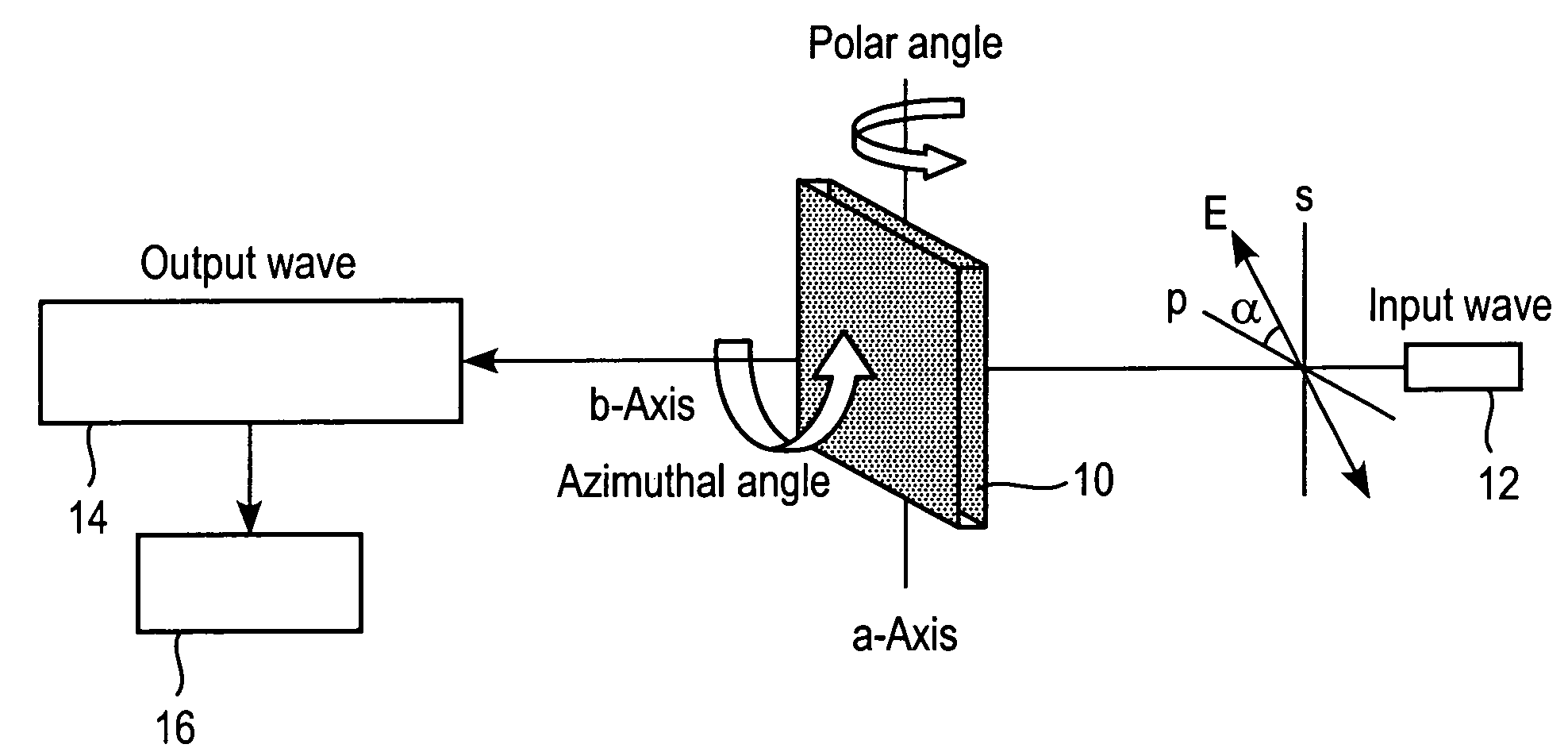
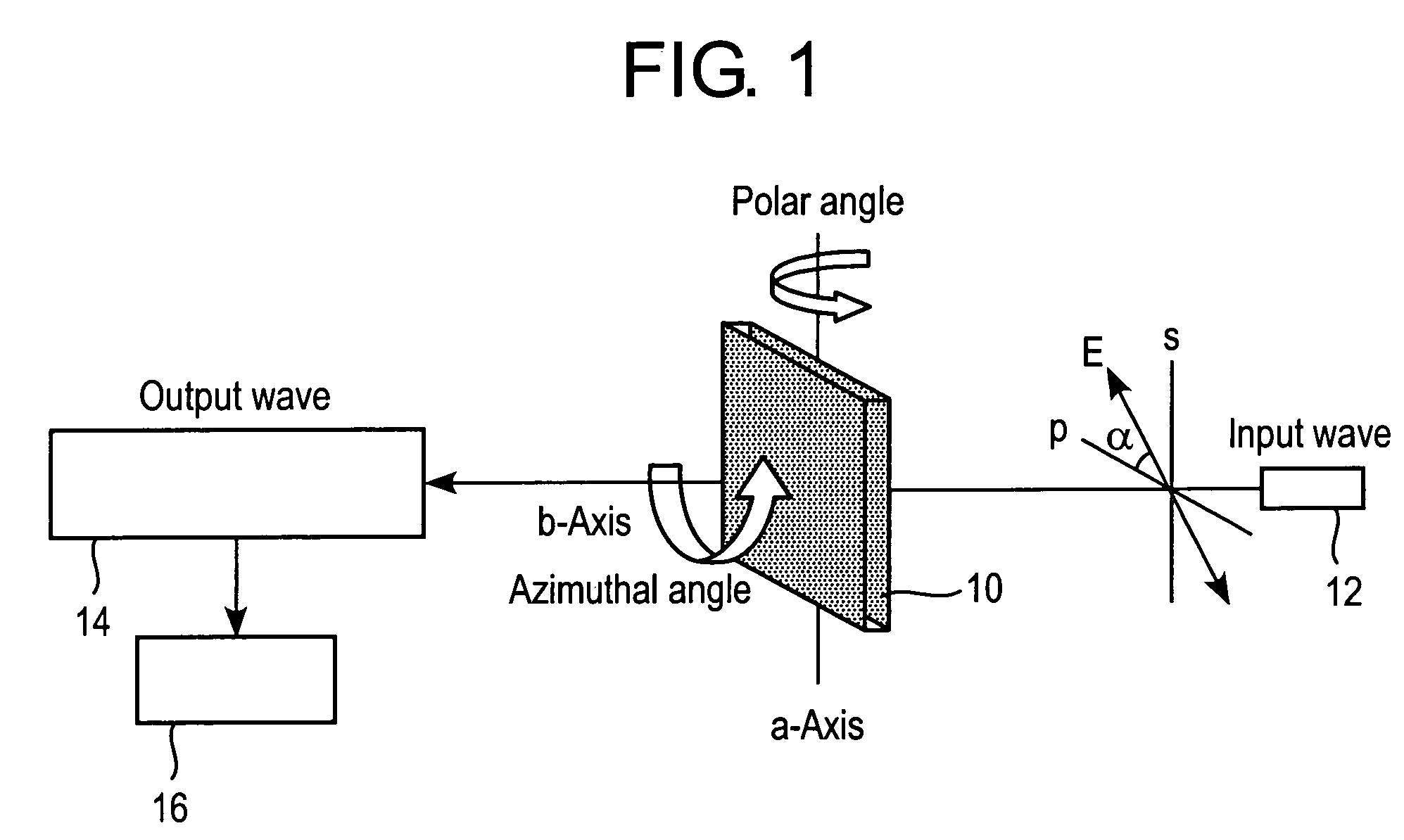
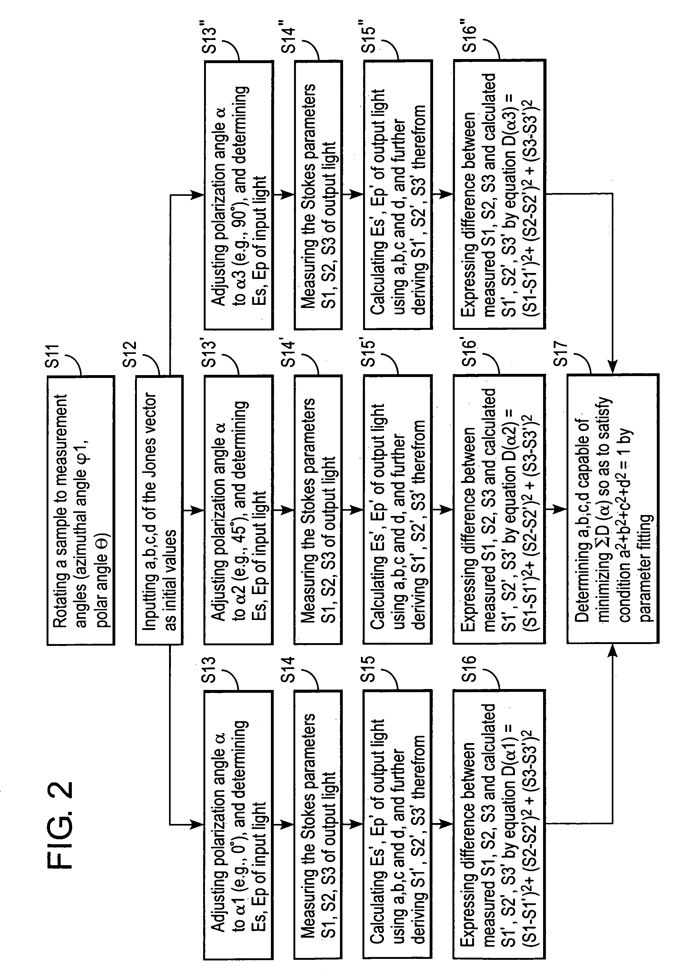
[0065] The Jones matrix of a polymer film was measured using an analyzer configured as shown in FIG. 1. A stretched polymer film (reference numeral 10 in the drawing) was used in the measurement, and the wavelength of the input light was 589 nm. A transmission ellipsometer (reference numeral 14 in the drawing) was used for measurement of the polarization state of the output light. The polymer film was measured by Abbe's method for mean refractive index, and the value was found to be 1.50. Polarization directions α of the input light was varied among 0°, 45°, 90° and 135°, and polarization states, or Stokes parameters (S1, S2, S3), were measured. Thus measured Stokes parameters were then fitted to three parameters using the equation (1) (more specifically, equation (1′)) and thereby a, b, c and d were determined. Such measurement was repeated while varying the polar angle θ and the azimuthal angle φ, to thereby determine the omnidirectional Jones matrix. The repetitive calculation me...

example 2

[0067] Using the Jones matrix obtained in Example 1, characteristics of an optical element, which is a liquid crystal display in this Example, were calculated. A liquid crystal layer employed herein was assumed as being in the vertically-aligned black state, or in other words being under no applied voltage, and the optical compensation in the black state was calculated. The liquid crystal layer was assumed as having a Δn·d of 300 nm, placed between the crossed polarizer plates, and the measured optical media were placed one by one between the upper / lower polarizer plates and the liquid crystal layer. Each optical medium was arranged so that the zero-degree direction of the measured polar angle is aligned in parallel with the transmission axis of each polarizer plate. Transmittance was then calculated while varying the polar angle in the direction 45° away from the transmission axis of the polarizer plate (so-called, off-axis state). The extended Jones matrix method shown in Y. Takah...


PUM


Abstract

A novel method for analyzing optical characteristics of an optical medium is disclosed. The method comprises illuminating an optical medium, having an input surface and an output surface of light, with at least three input light beams differed from each other in a polarization state, respectively from a direction inclined by a polar angle θ (0°<θ<90°) with regard to the input surface; obtaining polarization states of output light beams coming out from the output surface, corresponded to the input light beams; and determining the Jones matrix M which can satisfy the equation (1) below with polarization vectors of the input light beams and polarization vectors of the output light beams: (Es′Ep′)=Q′×M×Q×(EsEp)(1)where, Es and Ep are polarization vectors of s-polarization and p-polarization of an input light beam, respectively; Es′ and Ep′ are polarization vectors of s-polarization and p-polarization of a correspondent output light beam, respectively; Q is a dynamics matrix expressing change in a polarization state of an input light beam going into the optical medium from the air; and Q′ is a dynamics matrix expressing change in a polarization state of an output light beam going out the optical medium into the air.

Description

CROSS-REFERENCE TO RELATED APPLICATIONS [0001] This application claims benefit of priority under 35 USC 119 to Japanese Patent Application No. 2005-058434 filed Mar. 3, 2005. TECHNICAL FIELD OF THE INVENTION [0002] The present invention relates to a method for analyzing optical characteristics of optical mediums, and in particular to a method for analyzing optical characteristics of optical films useful for development and design of liquid crystal display devices. The present invention also relates to an apparatus for analyzing an optical medium employing the above-described analytical method, and a method for production monitoring. RELATED ART [0003] A liquid crystal display device usually comprises a liquid crystal cell and polarizing plates. The polarizing plate usually has protective films and a polarizing film, and is obtained typically by dying the polarizing film composed of a polyvinyl alcohol film with iodine, stretching, and being stacked on both surfaces thereof with the ...

Claims


Application Information

Patent Timeline
Patent Type & Authority Applications(United States)
IPC IPC(8): G01J4/00
CPCG01J4/04G01N21/21
Inventor SAITOH, YUKITO
Owner FUJIFILM CORP
Learn More