Fixing device and image forming apparatus

a fixing device and image forming technology, applied in the field of image forming apparatus, can solve the problems of poor thermal efficiency of halogen lamps, slow response (or low heat-up speed), requiring a fairly long time-period, and approaches have limitations for themselves, so as to reduce the generation of joule heat, effectively suppress the rise of temperature, and the effect of high fixing member heat-up ra

Inactive Publication Date: 2006-09-28
KYOCERA DOCUMENT SOLUTIONS INC
View PDF3 Cites 11 Cited by
  • Summary
  • Abstract
  • Description
  • Claims
  • Application Information

AI Technical Summary

Benefits of technology

[0024] Then, when the temperature of the temperature-sensitive metal layer becomes equal to or greater than the Curie temperature, the magnetic-field penetration depth becomes greater than the thickness of the temperature-sensitive metal layer (or 503×√{square root over (ρ / (1×f))}). Thus, the magnetic field passes over the temperature-sensitive metal layer and reaches the nonmagnetic metal layer, and the magnetic flux flows through the nonmagnetic metal layer. Further, in this state, the nonmagnetic metal layer made of a metal having a specific resistance value less than that of aluminum and formed to have a thickness allowing the nonmagnetic metal layer to be substantially free from a temperature rise due to the induction heating can reduce generation of Joule heat at lower level as compared with a temperature-sensitive metal layer made of aluminum.
[0025] As above, in the present invention, the nonmagnetic metal layer is made of a metal having a specific resistance value less than that of aluminum, and formed to have a thickness allowing the nonmagnetic metal layer to be substantially free from a temperature rise due to the induction heating. Thus, as compared with a case where aluminum is used as a material of the nonmagnetic metal layer, the fixing device can effectively suppress a temperature rise after the fixing device reaches a given temperature, while ensuring a high heat-up rate of the fixing member by means of induction heating.

Problems solved by technology

The halogen lamp has problems about poor thermal efficiency, and slow response (or low heat-up speed) requiring a fairly long time-period in a warming-up (initial heating) stage.
While various techniques for achieving reduction in heat capacity and wall thickness of the fixing roller have been developed as measures against these problems, such approaches have limitations for themselves.
On the other hand, the extremely high heat-up speed raises a new problem about excessive heating of the fixing roller.
However, the temperature sensor has difficulty in outputting a detection signal accurately in response to a temperature rise arising from the induction heating, and this time-lag or detection delay is likely to preclude prevention of excessive heating of the fixing roller.
In this state, if wider sheets are subjected to a fixing process, the accumulated heat will cause image defects, such as a so-called offset phenomenon that a toner image on one of the wider sheets is fusion-bonded onto the end regions of the fixing roller and then transferred onto the next wider sheet.
If the nonmagnetic metal layer is reduced in thickness without reasonable limit, a load will be increased (i.e. an eddy-current density will be increased) due to reduced eddy-current generation area, to cause difficulty in suppressing generation of Joule heat even when a magnetic field flows through the nonmagnetic metal layer after the temperature-sensitive metal layer becomes equal to or greater than a Curie temperature.
As a result, if a fixing process is continuously performed, even the induction heating-type fixing device disclosed in the Document D2 will be excessively heated to cause a problem about excessive temperature rise in opposite end regions of the fixing roller or a region except for a central region thereof where heat is released to sheets passing therethrough.

Method used


Image

  • Fixing device and image forming apparatus
  • Fixing device and image forming apparatus
  • Fixing device and image forming apparatus

Examples


first embodiment

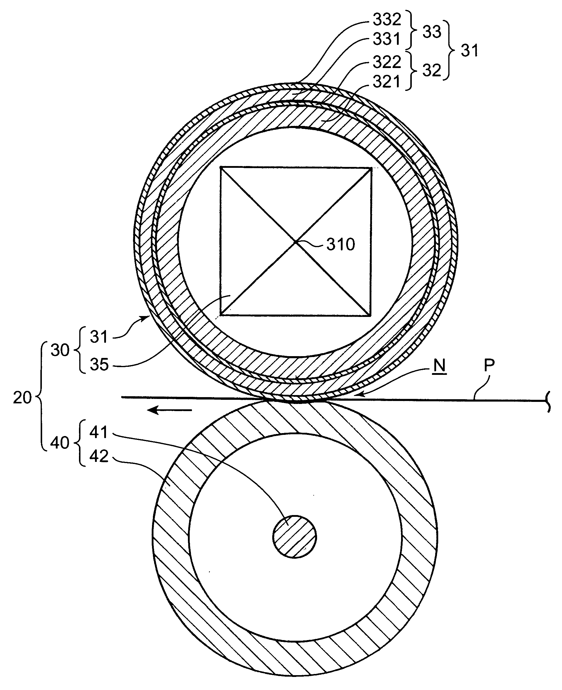
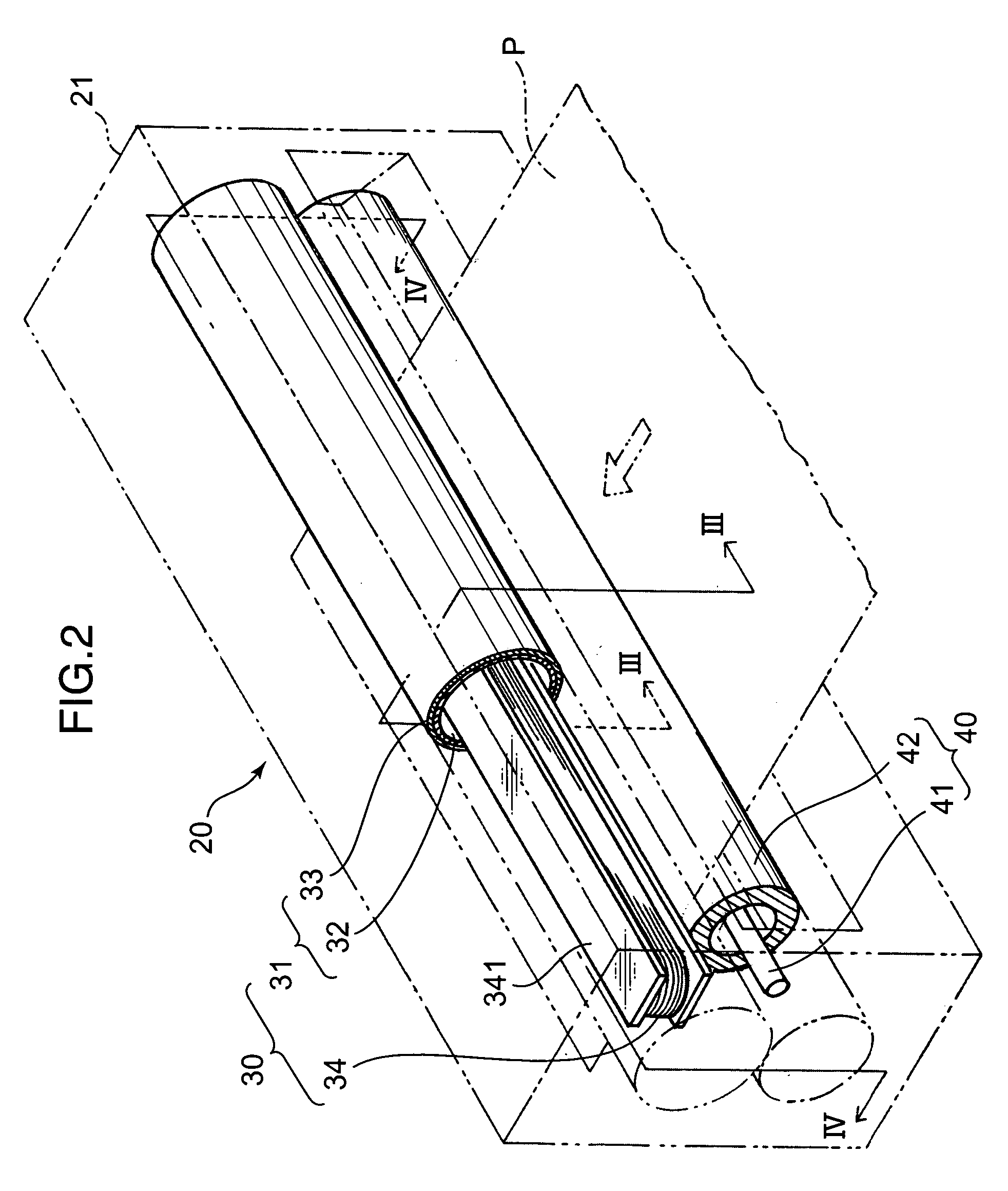
[0045]FIG. 2 is a schematic partly cutout perspective view showing a fixing device 20 according to the present invention. FIG. 3 is a sectional view taken along the line III-III in FIG. 2, and FIG. 4 is a sectional view taken along the line IV-IV in FIG. 2. In these figures, each thickness dimension of a fixing roller 31 and a pressing roller 42 is illustrated in an exaggerated manner. As shown in FIG. 2, the fixing device 20 comprises a fixing member 30, a pressing member 40 and a box-shaped housing 21 housing the fixing member 30 and the pressing member 40.

[0046] The fixing member 30 includes a tubular-shaped fixing roller 31 disposed in an upper region of an inner space of the housing 21, and an induction coil 34 housed in the fixing roller 31. More specifically, the fixing roller 31 is mounted to an upper portion of the housing 21 rotatably about a tube axis 310 (see FIG. 3) extending in a sheet-width direction orthogonal to a sheet-feeding direction (indicated by the two-dot-ch...

second embodiment

[0080] In the fixing device 20′ when the fixing belt 37 is circulatingly moved between the tension roller 35 and the fixing roller 36 by a rotational driving force of the tension roller 35, a magnetic flux is supplied from the induction coil 34′ to an outer surface of the fixing belt 37. Therefore, in a state before the metal layer 38 does not reach the Curie temperature (200° C.), the temperature-sensitive metal layer 382 is quickly heated up to the Curie temperature by Joule heat generated by an induced eddy current.

[0081] Thus, when a sheet P is fed to a nip zone N, the sheet P is moved leftward in FIG. 6A while being pressed and nipped between the pressing roller 42 and the fixing belt 37 circulating along the fixing roller body 362 which is elastically deformed. During this movement, the sheet P is subjected to the fixing process based on heat from the fixing belt 37.

[0082] Then, when the temperature of the temperature-sensitive metal layer 382 becomes equal to or greater tha...


PUM


Abstract

A fixing device (30) has a fixing member (30) adapted to be heated by induction heating based on a magnetic field from an induction coil (34). A pressing member (40) is disposed in contact with the fixing member (30) to define therebetween a nip zone (N) for passing a sheet (P) therethrough. The fixing member includes a heating layer (32). The heating layer (32) has a temperature-sensitive metal layer (321) formed on the side of the induction coil (34), and a nonmagnetic-metal layer (322) laminated onto the temperature-sensitive metal layer (321). The nonmagnetic metal layer (321) is made of a metal (copper (Cu)) having a specific resistance less than that of aluminum, and formed to have a thickness (30 μm) allowing the nonmagnetic metal layer to be substantially free from a temperature rise due to the induction heating.

Description

BACKGROUND OF THE INVENTION [0001] 1. Field of the Invention [0002] The present invention relates to an image forming apparatus, such as a copy machine, and a fixing device included therein, and more particularly to a fixing device for fixing a toner image on a transfer target in a manner based on an induction heating technique, and an image forming apparatus using the fixing device. [0003] 2. Description of the Related Art [0004] An image forming apparatus is designed to irradiate an outer peripheral surface of a photosensitive drum in a rotating state with an image information-based light beam so as to form an electrostatic latent image on the outer peripheral surface, and supply toner serving as developer to the latent image so as to a toner image. The toner image formed on the outer peripheral surface of the photosensitive drum is transferred onto a sheet serving as a transfer target fed thereto, and then the sheet is subjected to a fixing process based on heating in a fixing de...

Claims


Application Information

Patent Timeline
Patent Type & Authority Applications(United States)
IPC IPC(8): G03G15/20
CPCG03G15/2053G03G2215/20G03G15/2057
Inventor NANJO, YUZURU
Owner KYOCERA DOCUMENT SOLUTIONS INC
Why Eureka
Try Eureka