
Slipper having low frequency generator

a generator and low frequency technology, applied in the field of slippers, can solve the problems of low frequency stimulation effects, many inconveniences, and difficulty in maintenance, and achieve the effects of enhancing durability, preventing damage, and convenient carrying and storag

Inactive Publication Date: 2006-09-28
BEAUNIX
View PDF2 Cites 4 Cited by
  • Summary
  • Abstract
  • Description
  • Claims
  • Application Information

AI Technical Summary

Benefits of technology

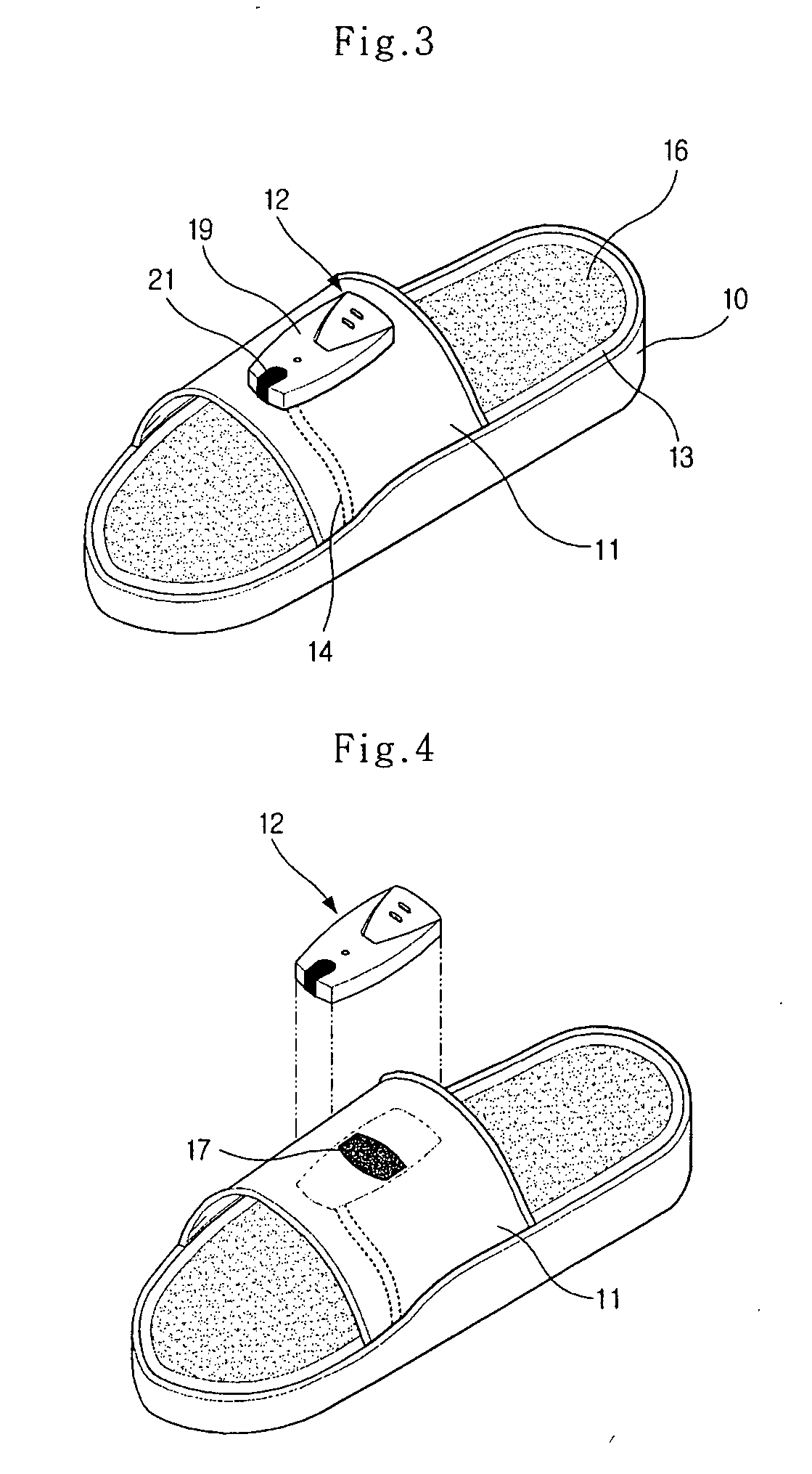
"The present invention provides a slipper with a low frequency generator that can enhance and activate the functions of intestines, kidneys, and other organs in the body by stimulating acupuncture points on the sole of a slipper user's foot using low frequency stimulation. The low frequency generator is installed at the slipper back part and can be charged using a power source. The low frequency generator is detachable from the slipper and can be easily carried and stored. The low frequency generator can be remotely controlled using a remote controller and provides many convenience to the user. The low frequency seat is made of a conductive material that can maintain certain moisture or can be charged using a rechargeable battery. The low frequency generator is installed at the slipper back part and can be easily detached. The low frequency generator is powered by a battery or a charging unit. The low frequency seat is made of a woven fabric or silicon material that can transfer low frequency signals to the foot bottom surface of the slipper user."

Problems solved by technology

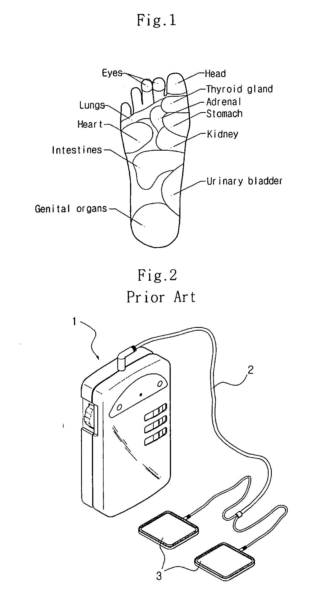
In the conventional low frequency therapy unit, since the conductive pad 3 is connected with the low frequency generator 1 through the power cable 2, many inconveniences occur when the user directly carries the low frequency therapy unit.
In this case, the effects of low frequency stimulation are decreased, and it is needed to recoat a conductive adhesive on the conductive pad 3, so that maintenance is not easy.

Method used


Image

  • Slipper having low frequency generator
  • Slipper having low frequency generator
  • Slipper having low frequency generator

Examples


Embodiment Construction

[0029] The preferred embodiments of the present invention will be described with reference to the accompanying drawings.

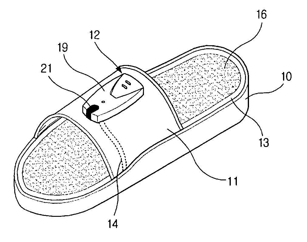
[0030] As shown in FIGS. 3. through 6, the slipper having a low frequency generation unit comprises a low frequency generator 12 which is installed at a slipper back part 11 of a slipper 10 (adaptable at common indoor shoes) for thereby generating a certain low frequency for stimulating human body in accordance with a control signal (inputted when operating the remote controller 20) externally inputted from a receiver 21; and a conductive low frequency seat 16 which is installed at the slipper bottom part 13 of the slipper 10 and is electrically connected with the low frequency generator 12 through a power cable 14 for thereby receiving a low frequency signal from the low frequency generator 12 and generating at a foot bottom surface of a user of the slipper 10 for thereby stimulating with low frequencies an acupuncture point of a corresponding nervous system.

[00...


PUM


Abstract

A slipper having a low frequency generation unit comprised a low frequency generator which is installed at a slipper back part of a slipper for thereby generating a certain low frequency for stimulating human body in accordance with a control signal externally inputted from a receiver, and a conductive low frequency seat which is installed at a slipper bottom part of the slipper for stimulating with low frequencies a foot bottom surface of a slipper user based on a low frequency signal transferred through a power cable electrically connected with the low frequency generator. With the above constructions, it is possible to enhance and activate the functions of intestines based on the stimulation of an acupuncture point distributed on the sole of a foot by pressurizing a corresponding nervous system of a foot bottom surface of a slipper user using a low frequency stimulation from the low frequency generator installed at a slipper back part or a slipper bottom part.

Description

BACKGROUND OF THE INVENTION [0001] 1. Field of the Invention [0002] The present invention relates to a slipper having a low frequency generator, which is capable of enhancing the functions of internal organs such as kidney, intestines, and etc. by stimulating an acupuncture point of a corresponding nervous system distributed on the sole of a slipper user's foot using the low frequencies generated by a low frequency seat, and in particular to a slipper having a low frequency generator constituted to enhance a user's health by activating the functions of internal organs of a corresponding nervous system by stimulating an acupuncture point of a corresponding nervous system distributed on the sole of a slipper user's foot based on a low frequency stimulation transferred from a low frequency generator installed at a slipper back part or a slipper bottom part. [0003] 2. Description of the Background Art [0004]FIG. 1 is a schematic view illustrating various nervous systems distributed on t...

Claims


Application Information

Patent Timeline
Patent Type & Authority Applications(United States)
IPC IPC(8): A61H1/00A43B3/10A43B3/35A61H39/00A61N1/32A61N1/36
CPCA43B3/0005A43B7/146A61H39/002A61N1/32A61N1/326A43B3/34A43B3/101A61H23/02
Inventor PARK, JEONG HOON
Owner BEAUNIX
Learn More