Surgical apparatus and tools for same

a technology for surgical equipment and tools, applied in the direction of secondary cells, applications, cell components, etc., can solve the problems of difficult cleaning, difficult to use thoroughly, and surgeons may not always have two hands free to insert and/or change tools, etc., to achieve convenient cleaning, not susceptible to damage, and easy to use

Inactive Publication Date: 2006-09-28
BRASSELER USA MEDICAL
View PDF29 Cites 1481 Cited by
  • Summary
  • Abstract
  • Description
  • Claims
  • Application Information

AI Technical Summary

Benefits of technology

[0010] Our invention remedies these and other drawbacks of the existing powered surgical apparatuses, and provides a surgical apparatus that is easy to use, easy to clean, and is not susceptibl

Problems solved by technology

While improvements have been made to powered surgical apparatuses in recent years, various drawbacks still remain.
One drawback is that many powered surgical apparatuses require at least two hands to install and/or change the tool attached to the apparatus.
However, during a surgical procedure, the surgeon may not always have two hands free to insert and/or change the tool.
Another drawback is that, in order to securely attach tools, existing powered surgical apparatuses typically employ a tool holder having a slot or other enclosure for insertion of the tool.
Such enclosures tend to have blind crevices, which are difficult to clean thoroughly.
In addition, such enclosures may obstruct the surgeon's view of the surgical sight during use.
Still another drawback of some existing surgical apparatuses is that their tool holders do not securely hold and seat the tool.
However, in this arrangement, the blade may not be securely held or seated in the tool holde

Method used


Image

  • Surgical apparatus and tools for same
  • Surgical apparatus and tools for same
  • Surgical apparatus and tools for same

Examples


Embodiment Construction

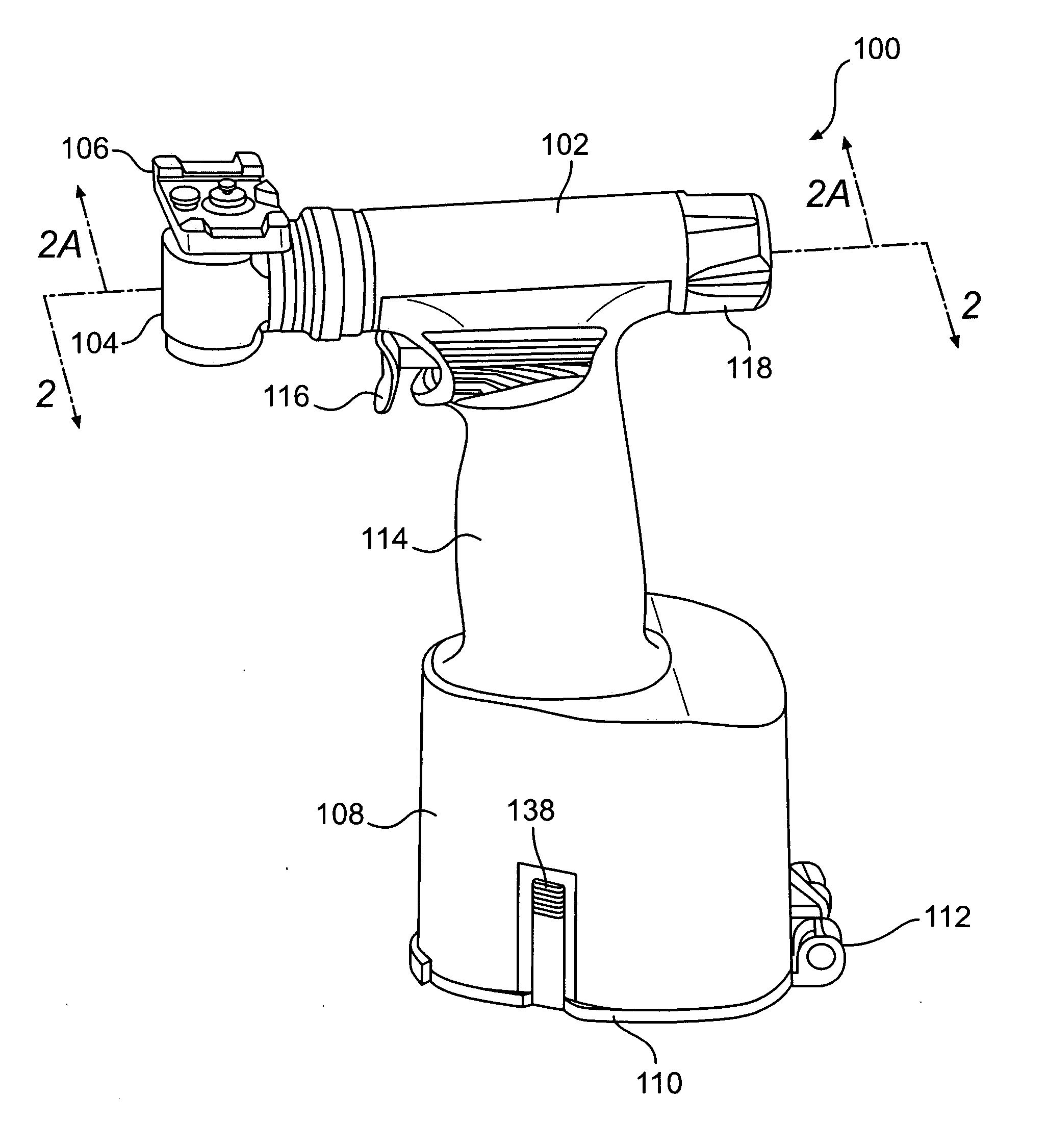
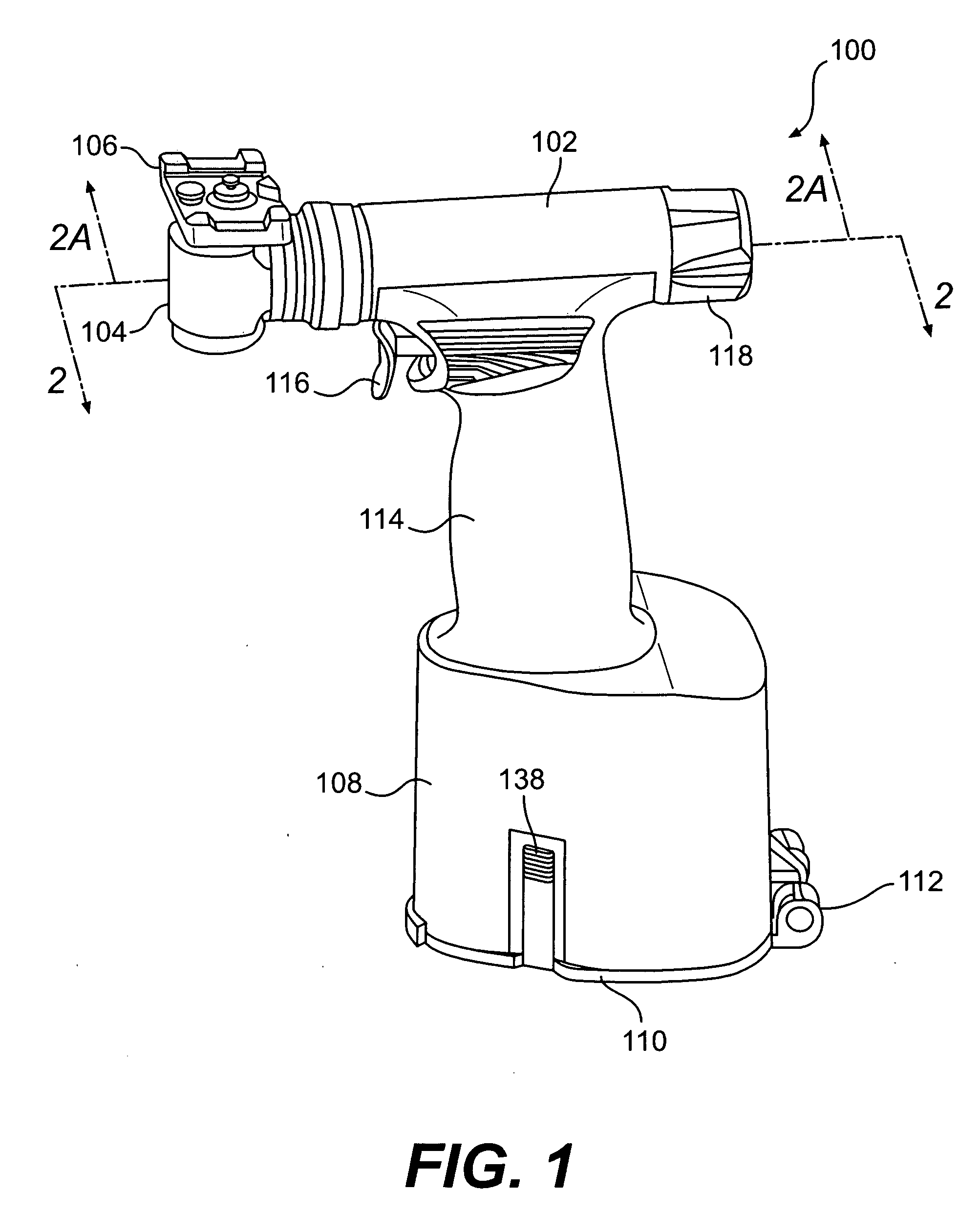
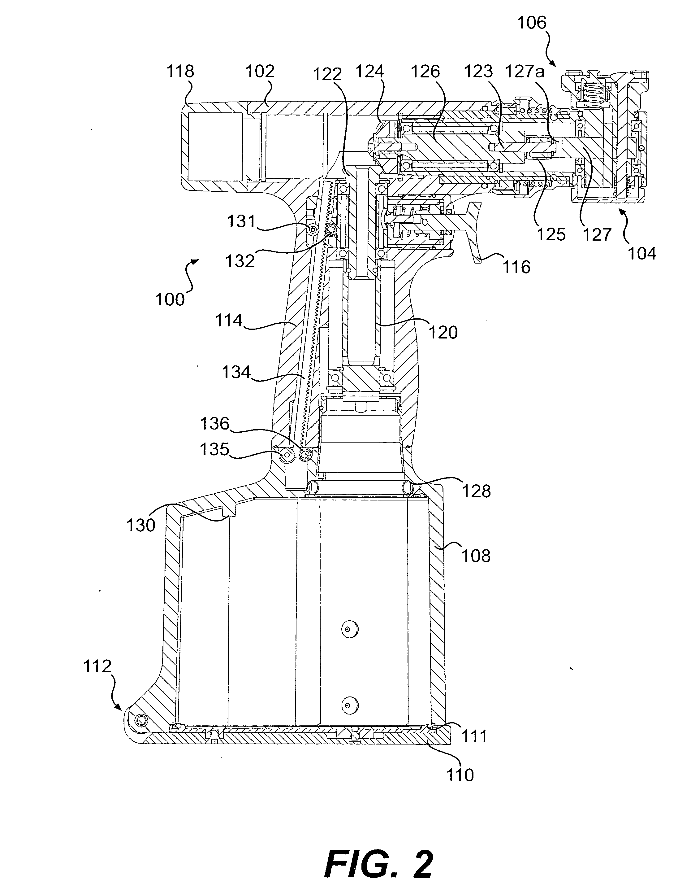
[0036] A surgical apparatus 100 according to one preferred embodiment of our invention is illustrated in FIGS. 1 through 5. As shown in FIG. 1, the surgical apparatus 100 generally includes a hand unit 102, an oscillator assembly 104 coupled to the hand unit 102, and, as shown in FIG. 2A, a power module 140 received in a receptacle 108 in the hand unit 102. As described further below, the oscillator assembly 104 rotates a tool holder 106 back-and-forth in an oscillatory manner to move a tool, such as the cutting tool shown in FIG. 4, in an arc. This type of device is generally known as a sagittal saw.

Hand Unit

[0037] With reference to FIGS. 1, 2, and 2A, the hand unit 102 is generally gun-shaped, having a handle 114 and a trigger 116 for gripping and actuating the surgical apparatus 100. The receptacle 108 of the hand unit 102 is provided with a lid 110 pivotally attached to the hand unit at a hinge 112. The lid 110 is pivotable between an open position (shown in FIG. 2A) for inse...


PUM


Abstract

A surgical power tool includes a hand unit and a tool holder. The tool holder engages a hub of a tool to hold the tool during use. One tool holder includes a substantially planar support surface, a pair of spaced-apart sidewalls protruding from the support surface, each sidewall having at least one tab extending from the sidewall toward the other of the sidewalls. A tool clamp, including a post protrudes from the support surface with an enlarged head at a distal end thereof. A lock button protrudes from the support surface, the lock button being depressible toward the support surface. Another tool holder includes an output shaft having a driven end and a free end, the free end of the output shaft having a slot formed therein. A collet is disposed coaxially with the output shaft and is rotatable relative thereto. The collet has a collet wall extending between the first and second ends of the collet. The collet has a plurality of slots in the first end of the collet, a plurality of grooves in an inner surface of the collet wall, and a plurality of internal ridges protruding from the inner surface of the collet wall.

Description

FIELD OF THE INVENTION [0001] Our invention relates generally to surgical apparatuses, and tools and power modules for the same, and to a method of preparing a surgical apparatus. More specifically, our invention relates to surgical apparatuses having tool holders that facilitate insertion of a tool, to tools having hubs that facilitate insertion of the tools in tool holders, to power modules having a power supply and an electric motor for use in surgical apparatuses, and to a method of preparing such a surgical apparatus for surgery. BACKGROUND OF THE INVENTION [0002] Orthopedic surgery requires a great degree of precision on the part of the surgeon. At the same time, orthopedic surgery often requires the removal or alteration of hard and / or tough materials, such as bone and tissue. Thus, orthopedic surgical tools must be sufficiently powerful and durable to cut or otherwise alter bone and tissue, while at the same time offering the degree of precision and control necessary to perf...

Claims


Application Information

Patent Timeline
IPC IPC(8): A61B17/00
CPCA61B17/14A61B17/162A61B17/1628A61B2017/00473A61B2017/00734A61B2019/4868H01M2/1055H01M2/30H01M10/425A61B17/148A61B2090/0813A61B17/142A61B17/144Y02E60/10H01M50/213
Inventor ESKRIDGE, DANA ALLENFOSTER, DENNIS L.HAIGHT, DOUGLAS WILLIAMKRIESE, LAURA A.
Owner BRASSELER USA MEDICAL
Why Eureka
Try Eureka