Computer system, data management method, and program

a computer system and data management technology, applied in computing, electric digital data processing, instruments, etc., can solve the problems of the inability to migrate in terms of file system and logical volume, and the inability to accurately predict the influence of migration

Inactive Publication Date: 2006-09-28
HITACHI LTD
View PDF12 Cites 29 Cited by
  • Summary
  • Abstract
  • Description
  • Claims
  • Application Information

AI Technical Summary

Benefits of technology

[0018] Therefore, a first object of the present invention is to provide a technology that allows LU migration in terms of a file system and a logical volume in a host computer which provides a file system function and a logical volume function.
[0019] Also, a second object of the present invention is to provide a technology that allows effective migration by determining a migration method based on highly-accurate prediction of a migration influence.
[0033] Also, according to the present invention, effective migration is possible by determining a migration method based on highly-accurate prediction of a migration influence.

Problems solved by technology

Incidentally, the above-described conventional technologies have the problems as follows.
First, in a host computer which provides a file system function and a logical volume function, LU migration in terms of the file system and the logical volume is difficult.
This is because the characteristic of the physical storage device which forms the LU to be used cannot be accurately known.
However, in the disk array system as disclosed in the patent document 1, a plurality of LUs having different processing speeds and different storage capacities can be configured in the same system, which makes it difficult to classify these LUs depending on their operation speeds.
The second problem is that, when the LU migration in terms of the file system and the logical volume is desired, it is difficult to predict an influence on the system after migration.

Method used


Image

  • Computer system, data management method, and program
  • Computer system, data management method, and program
  • Computer system, data management method, and program

Examples


first embodiment

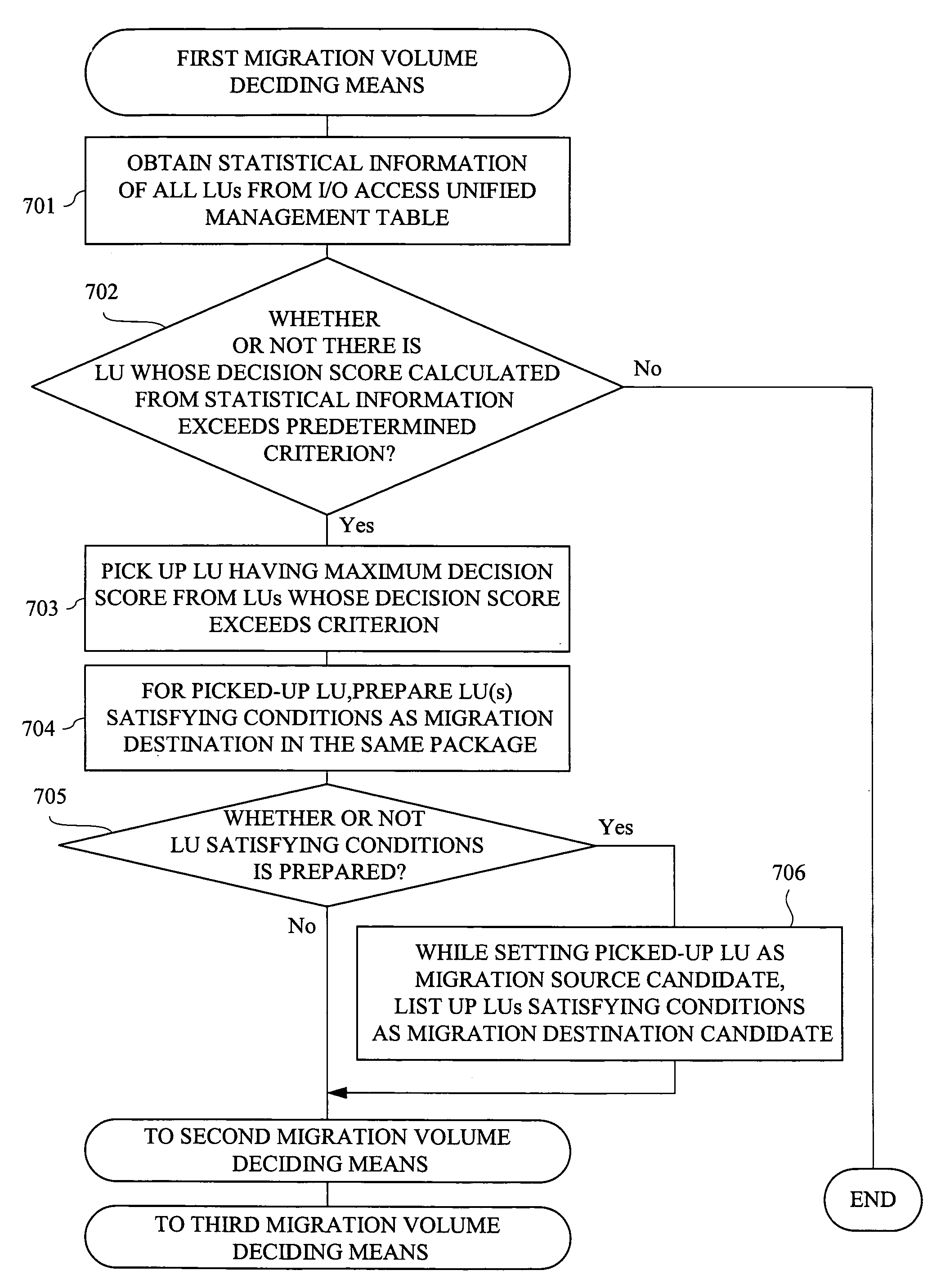
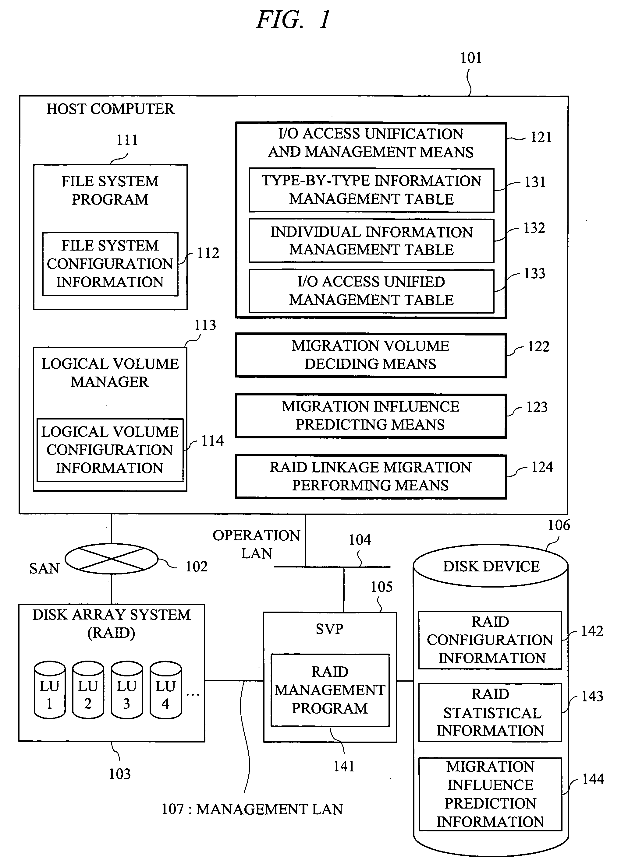
[0053]FIG. 1 is a schematic drawing of the structure of a computer system according to a first embodiment of the present invention. The computer system according to the present embodiment typically includes a host computer 101, a disk array system 103, a Service Processor (SVP) 105, and a disk device 106.

[0054] The host computer 101 and the disk array system 103 are connected to each other via a Storage Area Network (SAN) 102, which is a network for storage. To the disk array system 103, the SVP 105 for disk management is connected via a management-purpose Local Area Network (management LAN) 107. To the SVP 105, the disk device 106 used to store various information outputted by a RAID management program 141 operating on the SVP 105 is connected.

[0055] The information outputted by the RAID management program 141 typically includes RAID configuration information 142, RAID statistical information 143, and migration influence prediction information 144. The RAID configuration informat...

second embodiment

[0098]FIG. 13 is a schematic drawing of the configuration of a computer system according to a second embodiment of the present invention. In the above-described first embodiment, the RAID configuration information 142 managed by the SVP 105 and other information are used on the host computer 101 side. Therefore, the I / O access unified management table 133 is retained on the host computer side and used in the LU migration. In contrast to the above-described first embodiment, in the present embodiment, the file system configuration information 112 managed by the file system program 111 and the logical volume configuration information 114 managed by the logical volume manager 113 in the host computer 101 are used in the SVP 105. By doing so, effects similar to those in the above-described first embodiment can be achieved.

[0099] Hereinafter, the present embodiment will be described by showing the differences from the above-described first embodiment.

[0100] In the present embodiment, t...

third embodiment

[0102]FIG. 14 is a schematic drawing of the configuration of a computer system according to a third embodiment of the present invention. A difference between the present embodiment and the above-described first and second embodiments is that LU migration is performed in the first and second embodiments while LU copying is performed in the present embodiment. In the present embodiment, the copied LU is used to form a logical volume as a mirror volume by establishing the correspondence between the copy-source LU and a copy-destination LU in the logical volume manager 113 on the host computer 101 side.

[0103] Hereinafter, the present embodiment will be described by mainly showing the differences from the above-described first embodiment.

[0104] Since an object of the present embodiment is to perform copying in units of LU, the migration volume deciding means 122 and the migration influence predicting means 123 in the above-described first embodiment are not required. Accordingly, the R...


PUM


Abstract

A technology capable of achieving the LU migration in terms of a file system and a logical volume and the effective migration in a host computer which provides a file system function and a logical volume function is provided. A computer system has I / O access unification and management means that obtains RAID configuration information and RAID statistical information in a disk array system and manages an I / O access unified management table in which file system configuration information and logical volume configuration information managed by an OS are unified. Also, the computer system has migration volume deciding means that determines a migration method based on the I / O access unified management table, migration influence predicting means that obtains migration influence prediction information, and RAID linkage migration performing means.

Description

CROSS-REFERENCE TO RELATED APPLICATION [0001] The present application claims priority from Japanese Patent Application No. JP 2005-85250 filed on Mar. 24, 2005, the content of which is hereby incorporated by reference into this application. TECHNICAL FIELD OF THE INVENTION [0002] The present invention relates to a computer system which provides a file system and a logical volume. More particularly, it relates to a technology effectively applied to a file system management method and program for changing the configuration of the file system. BACKGROUND OF THE INVENTION [0003] For example, in many computer systems, an access from a user program or the like to a secondary storage is performed through a plurality of abstraction and virtualization layers by software and hardware. With these abstraction and virtualization, convenience of an access to a volume of the secondary storage is enhanced. Typical abstraction and virtual layers are a file system and a logical volume provided by an ...

Claims


Application Information

Patent Timeline
Patent Type & Authority Applications(United States)
IPC IPC(8): G06F13/28G06F12/16
CPCG06F3/061G06F3/0647G06F3/0665G06F3/067
Inventor UKAI, TOSHIYUKITAKAMOTO, YOSHIFUMISHIMIZU, MASAAKIYASUDA, YOSHIKO
Owner HITACHI LTD
Why Eureka
Try Eureka