Substrate processing apparatus

a processing apparatus and substrate technology, applied in the direction of cleaning process and apparatus, chemistry apparatus and processes, cleaning using liquids, etc., can solve the problems of water marks on the substrate, difficulty in uniform and efficient drying of the plurality of substrates, and insufficient drying of the substrate, so as to achieve uniform and efficient drying of the substrate

Inactive Publication Date: 2006-10-05
DAINIPPON SCREEN MTG CO LTD
View PDF6 Cites 8 Cited by
  • Summary
  • Abstract
  • Description
  • Claims
  • Application Information

AI Technical Summary

Benefits of technology

[0021] It is an object of the present invention to provide a substrate processing apparatus capable of drying a substrate uniformly and efficiently.
[0022] It is another object of the present invention to provide a substrate processing apparatus capable of preventing inadequate drying of a substrate.

Problems solved by technology

In addition, the pure water adhered to the substrates will cause formation of water marks on the substrate when naturally dries.
When the dew points do not distribute uniformly in the atmosphere around the substrate W as described above, it is difficult to dry the plurality of substrates W uniformly and efficiently.
Such turbulence at the liquid surface TL1 may cause inadequate drying of the substrate W.

Method used


Image

  • Substrate processing apparatus
  • Substrate processing apparatus
  • Substrate processing apparatus

Examples


first embodiment

(1) First Embodiment

[0072] (1-a) Structure and Operation of Substrate Processing Apparatus

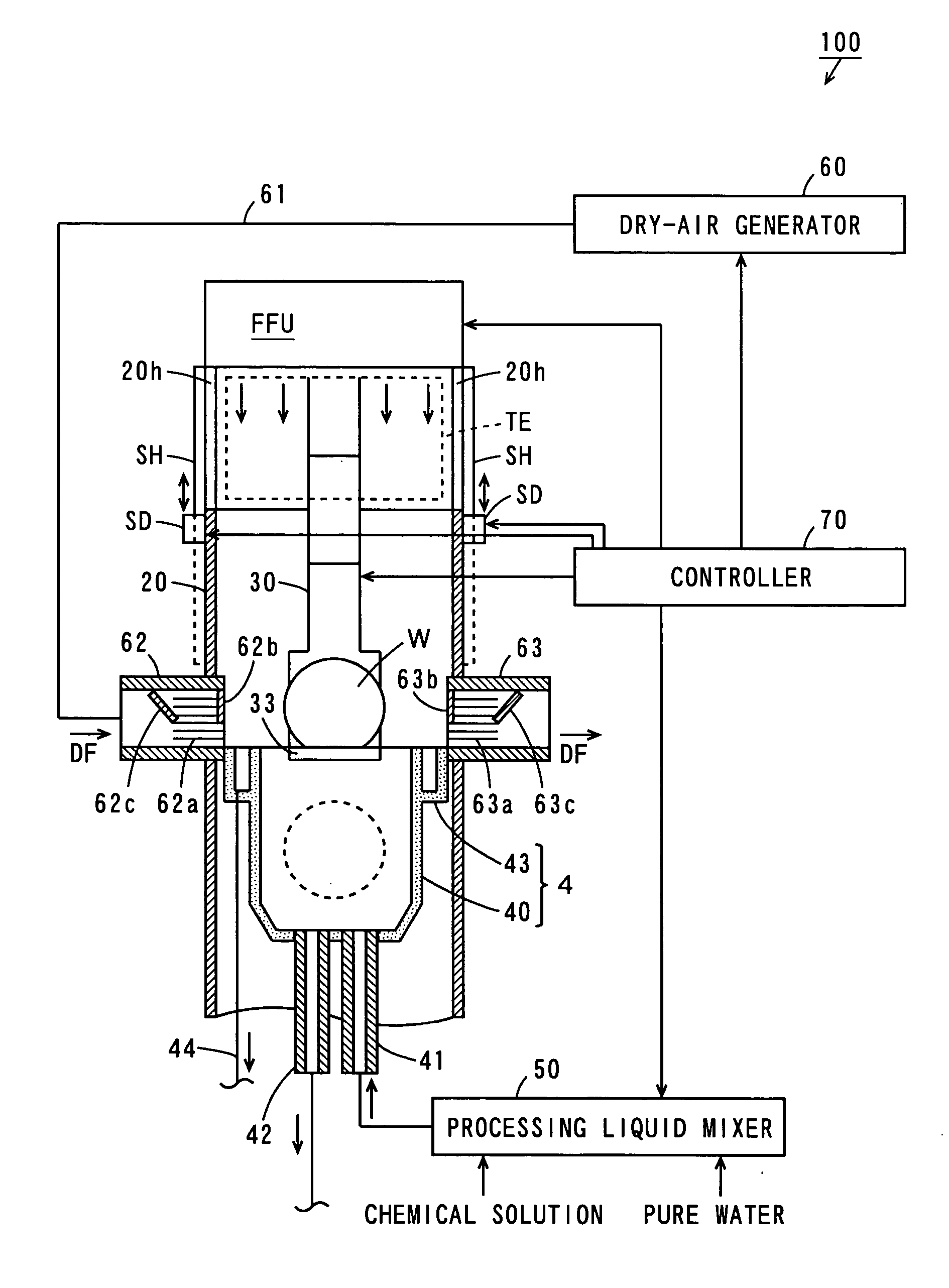
[0073]FIG. 1 is a schematic cross section view showing a structure of a substrate processing apparatus according to a first embodiment of the present invention. As shown in FIG. 1, a substrate processing apparatus 100 according to the present embodiment includes a processing tank 4, a downflow duct 20, a substrate shifting mechanism 30, a processing liquid mixer 50, a dry-air generator 60, a controller 70 and a fan filter unit FFU.

[0074] The fan filter unit FFU is disposed in an upper part of the downflow duct 20. The fan filter unit FFU has a fan and a filter. As the fan of the fan filter unit FFU operates, a clean descending gas flow (downflow) generates in the downflow duct 20.

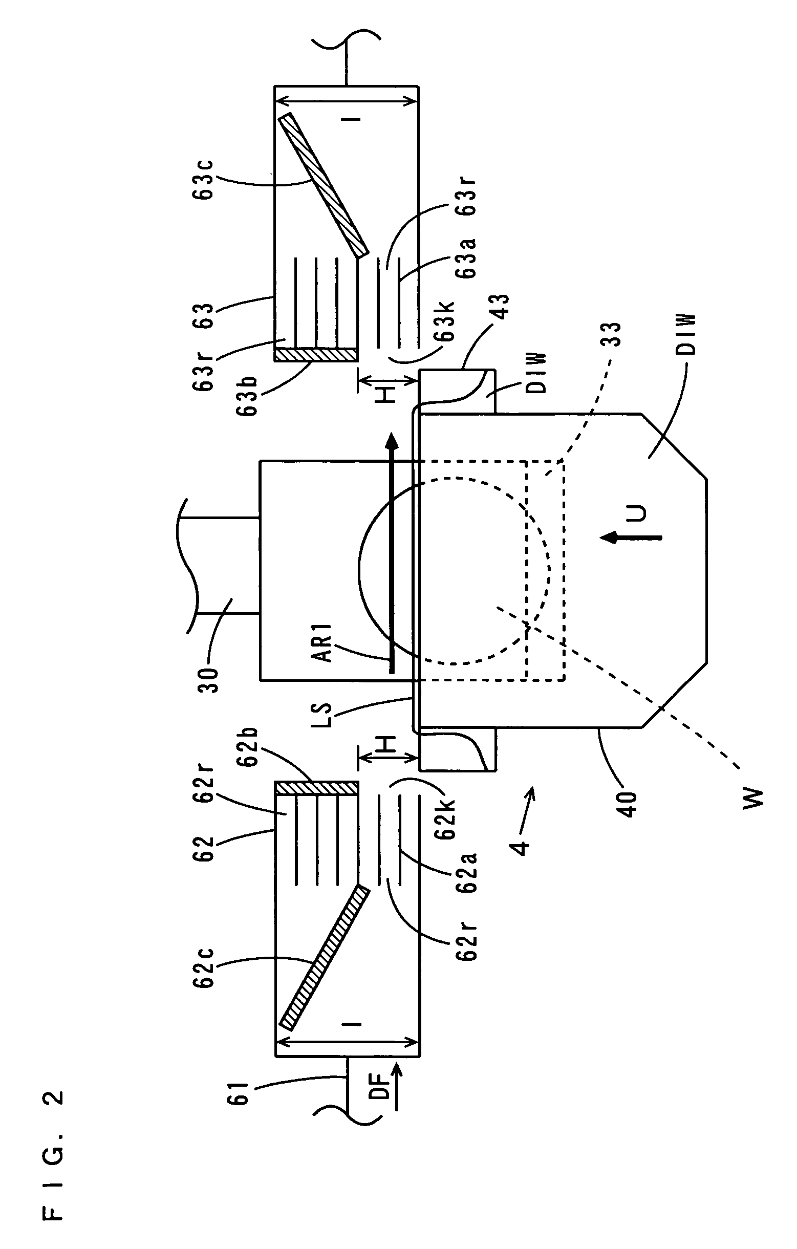
[0075] The processing tank 4 is disposed in a lower part within the downflow duct 20. The processing tank 4 is made up of an inner tank 40 capable of accommodating a plurality of substrates W, and an outer tank 43 f...

second embodiment

(2) Second Embodiment

[0159] (2-a) Structure and Operation of Substrate Processing Apparatus According to Second Embodiment

[0160] A substrate processing apparatus according to the second embodiment differs in the following points in structure and operation from the substrate processing apparatus 100 according to the first embodiment.

[0161]FIG. 6 is a schematic cross-section view showing a structure of a substrate processing apparatus according to the second embodiment. As shown in FIG. 6, the substrate processing apparatus 100 according to the present embodiment has a dry-air supplying duct 64 provided above the downflow duct 20 in addition to the structure of the substrate processing apparatus 100 according to the first embodiment.

[0162] Further, the partition plates 62b, 62c, 63b, 63c described in the first embodiment are not attached to the dry-air supplying duct 62 and the dry-air exhaust duct 63. In the dry-air supplying duct 64, ventilation guides 64a is provided as is the c...

third embodiment

(3) Third Embodiment

[0173] (3-a) Structure and Operation of Substrate Processing Apparatus

[0174]FIG. 8 is a schematic cross section view showing a structure of a substrate processing apparatus according to the third embodiment. As shown in FIG. 8, a substrate processing apparatus 100 according to the present embodiment has a processing tank 4, a downflow duct 20, a substrate shifting mechanism 30, a processing liquid mixer 50, a dry-air generator 60, a controller 70 and a fan filter unit FFU.

[0175] Above the downflow duct 20, the fan filter unit FFU is disposed. The fan filter unit FFU has a fan and a filter. As the fan of the fan filter unit FFU operates, a clean descending gas flow (downflow) is generated in the downflow duct 20.

[0176] The processing tank 4 is disposed in a lower part within the downflow duct 20. The processing tank 4 is made up of an inner tank 40 capable of accommodating a plurality of substrates W, and an outer tank 43 formed so as to surround an upper circu...


PUM


Abstract

A dry-air supplying duct and a dry-air exhaust duct are opposite each other across a processing tank. Inside the dry-air supplying duct, a plurality of ventilation guides are provided that extend horizontally by a predetermined length from an end of the dry-air supplying duct, and a plurality of ventilation paths are formed by the plurality of ventilation guides. To an end of the dry-air supplying duct, a partition plate is attached such that it blocks a part of the plurality of ventilation paths. Also inside the dry-air supplying duct, a partition plate is attached such that it blocks a part of the plurality of ventilation paths. These partition plates are disposed in upper part of the dry-air supplying duct. As a result, an opening for injection of dry air is formed in a lower part of the dry-air supplying duct.

Description

BACKGROUND OF THE INVENTION [0001] 1. Field of the Invention [0002] The present invention relates to a substrate processing apparatuse that performs various processes on a substrate. [0003] 2. Description of the Background Art [0004] Conventionally, substrate processing apparatuses are used for performing various processes on substrates such as semiconductor wafers, glass substrates for photomask, glass substrates for liquid crystal display, glass substrates for plasma display, substrates for optical disc, substrates for magnetic disc, substrates for magneto-optic disc and the like. [0005] One known substrate processing apparatus performs a cleaning process while a plurality of substrates are dipped in a processing tank which stores a processing liquid (see JP 11-354488 A, for example). In this substrate processing apparatus, surfaces of the substrates are subjected to a cleaning process with a chemical solution and pure water in the processing tank. The substrates having subjected ...

Claims


Application Information

Patent Timeline
Patent Type & Authority Applications(United States)
IPC IPC(8): B08B3/10
CPCB08B3/10H01L21/67034H01L21/67028B08B3/102
Inventor IWATA, TOMOMI
Owner DAINIPPON SCREEN MTG CO LTD
Why Eureka
Try Eureka