Torsion beam type rear suspension

Inactive Publication Date: 2006-10-05
MAZDA MOTOR
View PDF0 Cites 11 Cited by
  • Summary
  • Abstract
  • Description
  • Claims
  • Application Information

AI Technical Summary

Benefits of technology

[0008] It is therefore an object of the present invention to provide a torsion beam type rear suspension having a spring seat which is fixed to not only a training aim but also a torsion beam in such a manner as to improve the supporting rigidity of the spring seat relative to a coi

Problems solved by technology

However, this technique has its own limits.
Moreover, if the rigidities of the spring seat and the trailing arm are improperly increased, a b

Method used


Image

  • Torsion beam type rear suspension
  • Torsion beam type rear suspension
  • Torsion beam type rear suspension

Examples


Example

[0018] With reference to the accompanying drawings, an preferred embodiment of the present invention will now be described.

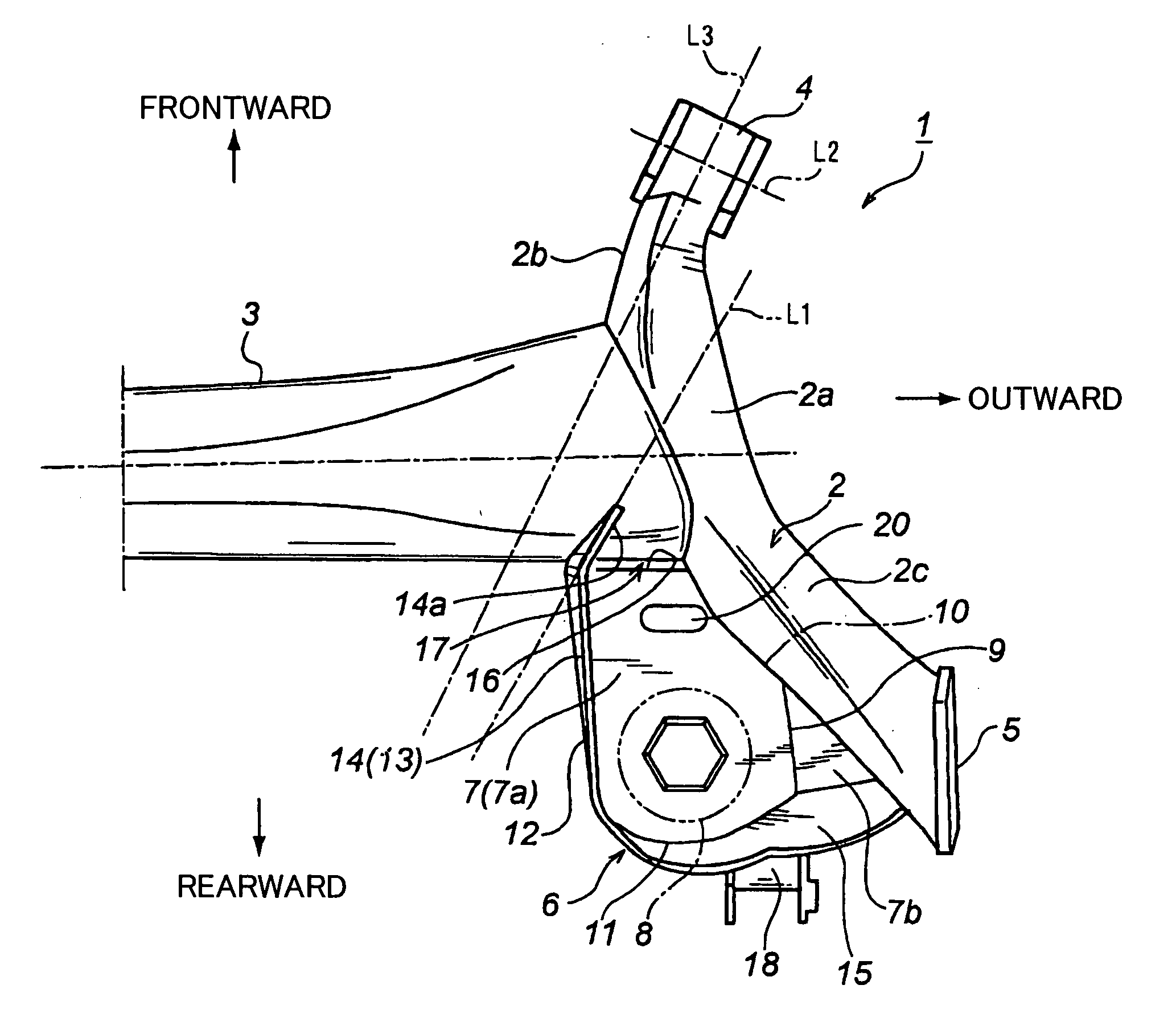
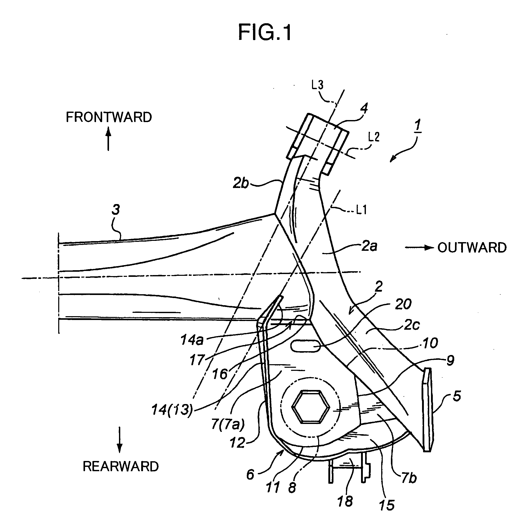
[0019]FIG. 1 is a fragmentary top plan view showing a right portion of a torsion beam type suspension according to one embodiment of the present invention, which is applied to a rear suspension for a vehicle. The torsion beam type rear suspension 1 comprises a pair of right and left trailing arms 2 disposed to extend in a frontward / rearward or longitudinal direction of a vehicle body, and a torsion beam 3 disposed to extend in a width or lateral direction of the vehicle body. Each of opposed lateral ends of the torsion beam 3 is welded to a longitudinally central portion 2a of a corresponding one of the trailing arms 2 to form a structure where the pair of trailing arms 2 are connected, respectively, to the opposed lateral ends of the torsion beam 3.

[0020] As with the structure disclosed in the Patent Publication 1 (Japanese Patent Laid-Open Publication No. 20...


PUM


Abstract

Disclosed is a torsion beam type rear suspension which comprises a pair of right and left trailing arms (2), a torsion beam (3), and a spring seat (6) disposed in a corner region defined at a junction between each of the lateral ends of the torsion beam and a rear portion (2c) of a corresponding one of the trailing arms to form a mounting seat for a coil spring (8). A vertical flange (13) is formed along a laterally inner edge (12) of the spring seat to have a longitudinally front edge extending vertically along a rear side surface of the torsion beam. The spring seat has a first region (7b) of disposed opposed to the corresponding trailing arm and fixed thereto approximately in its entirety, and a second region (16) disposed opposed to the torsion beam and fixed thereto only through the vertical flange. The torsion beam type rear suspension of the present invention can improve the supporting rigidity of the spring seat relative to a coil spring without increasing the rigidities of the spring seat and trailing arm themselves, while allowing the risk of stress concentration occurring at an end of the torsion beam to be reduced, so as to achieve increased chassis rigidity and adequately maintain suspension functions.

Description

BACKGROUND OF THE INVENTION [0001] 1. Field of the Invention [0002] The present invention relates to a torsion beam type rear suspension. [0003] 2. Description of the Related Art [0004] A torsion beam type suspension has a structure which comprises a torsion beam extending in a width or lateral direction of a vehicle body, and a pair of right and left arms each extending in a frontward / rearward or longitudinal direction of the vehicle body, wherein the torsion beam has opposite ends each connected to a longitudinally central portion of a corresponding one of the arms. This torsion beam type suspension is widely employed as a rear suspension for FF (front engine / front-wheel drive) compact vehicles. Generally, in the torsion beam type rear suspension employed in such FF compact vehicles, each of the arms is designed as a so-called trailing arm having a front end connected to a vehicle body and a rear end mounting a rear wheel, as disclosed in the following Patent Publication 1. Furthe...

Claims


Application Information

Patent Timeline
IPC IPC(8): B60G21/05B60G11/20
CPCB60B35/02B60B2310/206B60B2310/302B60B2360/102B60B2360/1458B60G2206/20B60G21/051B60G2202/136B60G2204/124B60G2204/43B60G2206/014B60B2900/311
Inventor KUSAKA, YUKIHARADA, KAZUO
Owner MAZDA MOTOR
Why Eureka
Try Eureka