Structure for arrangement of engine-associated vehicle components

a technology for vehicle components and structures, applied in monocoque constructions, roofs, transportation and packaging, etc., can solve the problems of affecting the layout of engine rooms, difficult to provide a sufficient crush space, and the tendency to decrease driving stability, so as to achieve effective improvement of driving stability and air intake performan

Inactive Publication Date: 2006-10-05
MAZDA MOTOR CORP
View PDF9 Cites 20 Cited by
  • Summary
  • Abstract
  • Description
  • Claims
  • Application Information

AI Technical Summary

Benefits of technology

[0009] In light of the aforementioned problems of the prior art, it is an object of the invention to provide a simple structure for arrangement of engine-associated componen

Problems solved by technology

However, the battery used as a power supply unit of the vehicle has a specific size and weight, so that there can arise a problem with respect to engine room layout if the battery is installed at the front of the engine body.
Additionally, if the battery is installed at a frontal part of the vehicle body, it becomes difficult to provide a sufficient crush space which is critical in the event of a collision.
Moreover, if the battery is located at a position offset to the left or right of the vehicle body, there can arise a problem that driving stability tends to decrease due to an increase in yaw moment of

Method used


Image

  • Structure for arrangement of engine-associated vehicle components
  • Structure for arrangement of engine-associated vehicle components
  • Structure for arrangement of engine-associated vehicle components

Examples


Embodiment Construction

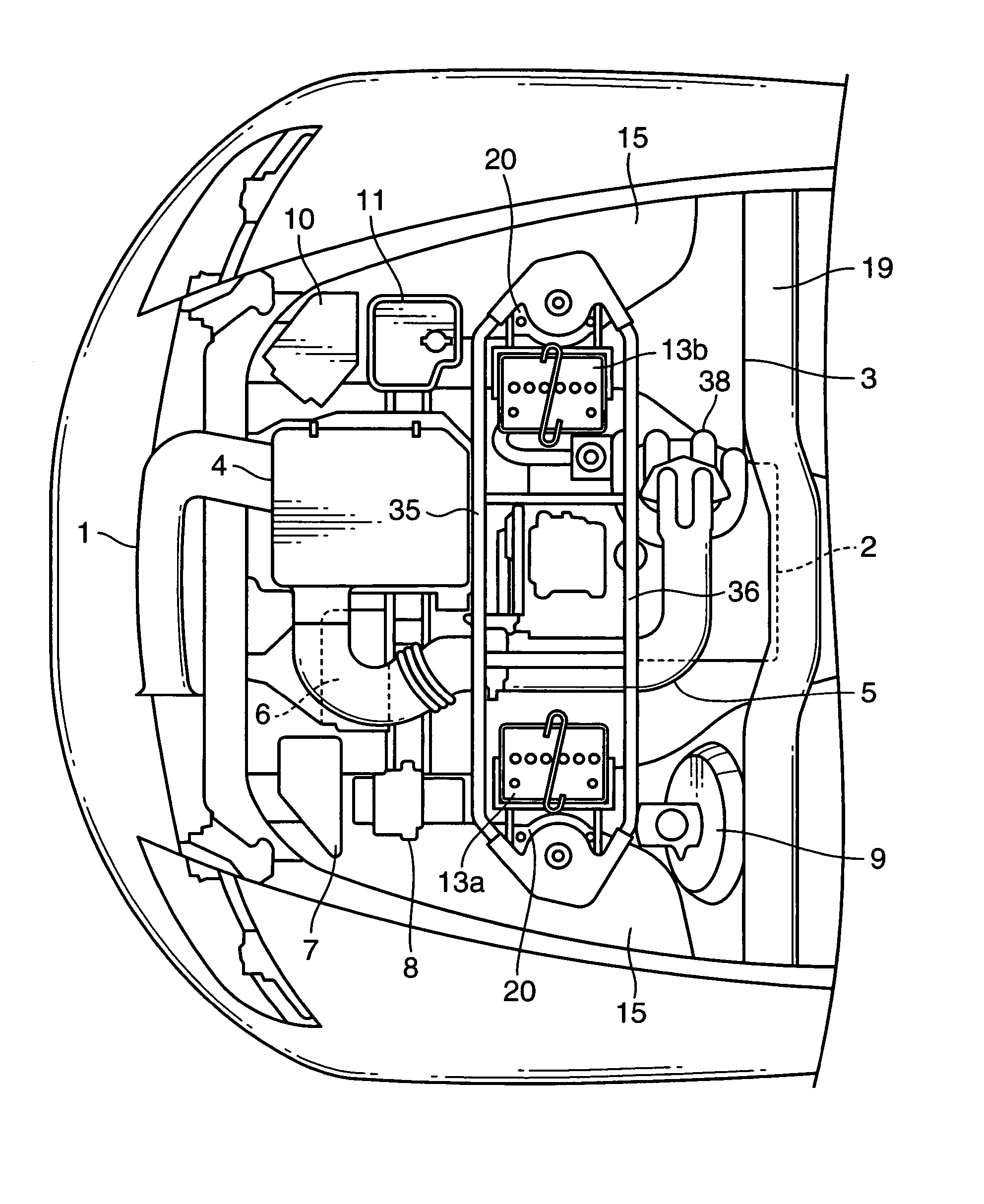
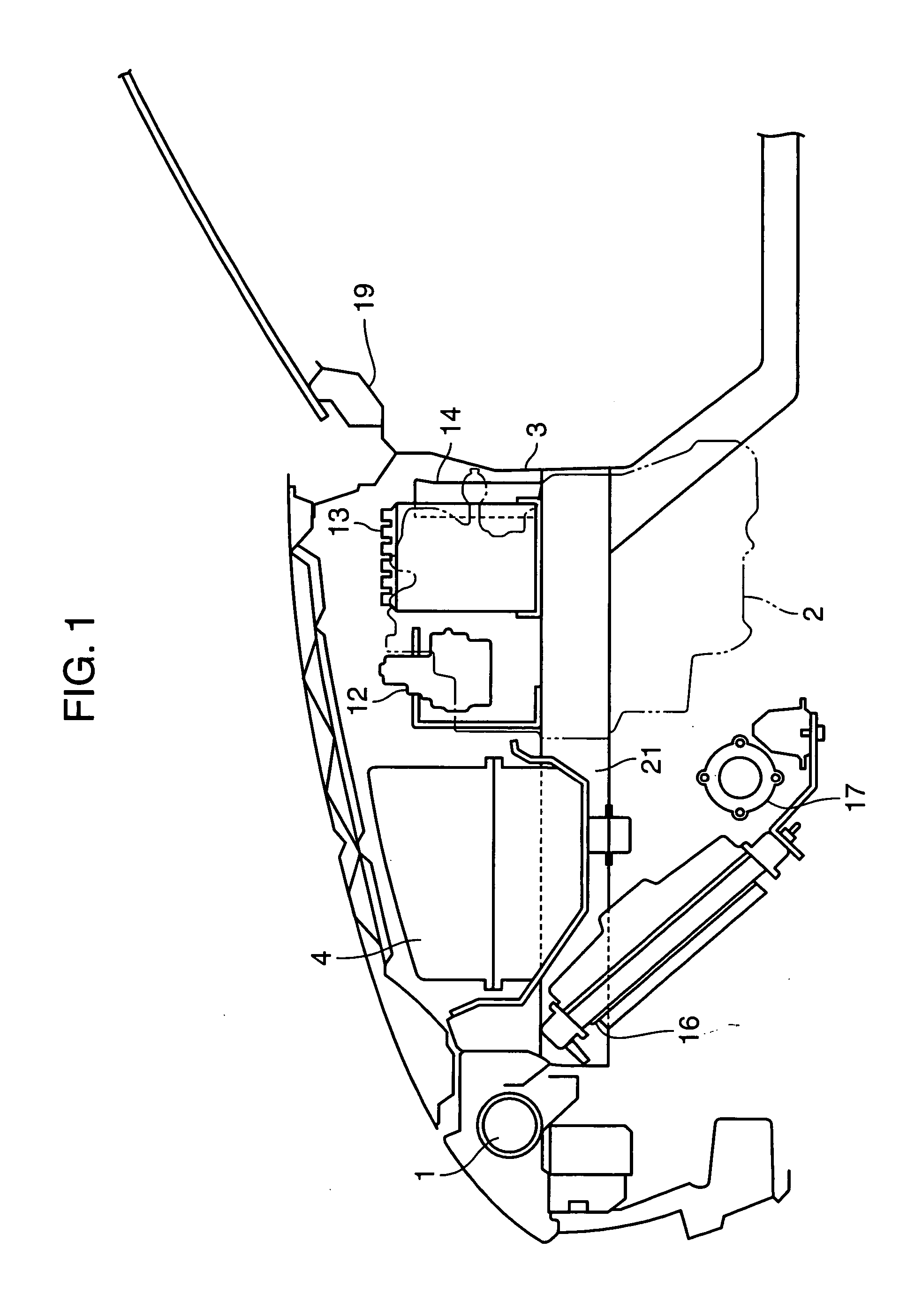
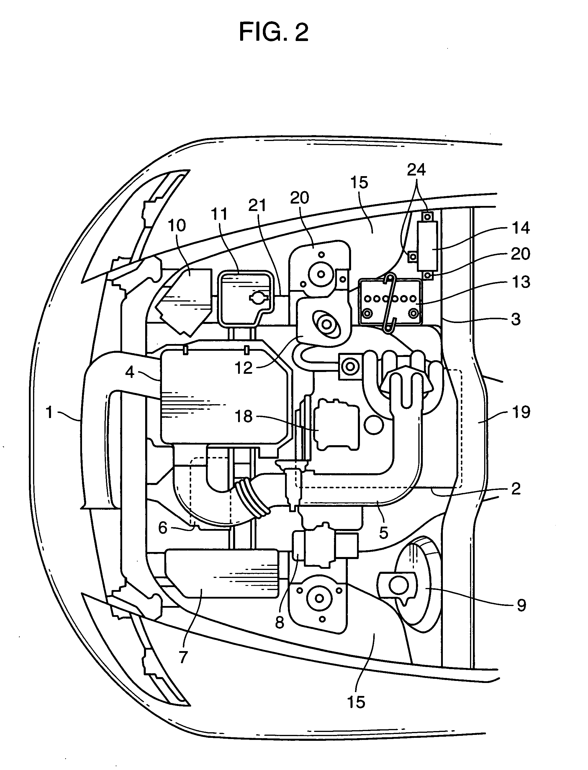
[0027]FIGS. 1 and 2 are diagrams showing a structure for arrangement of engine-associated components provided in an engine room of a vehicle according to a preferred embodiment of the invention. As illustrated in these Figures, the engine room accommodates from front to back a fresh air duct 1 serving as a fresh air conduit located at a forward part of the engine room, an air cleaner 4, and an engine body 2 which is a rotary engine located between the air cleaner 4 and a dash panel 3. These components are arranged such that fresh air drawn in through the fresh air duct 1 while the vehicle is running is supplied to the engine body 2 through the air cleaner 4 and an intake air passage 5.

[0028] As shown in FIG. 2, there are provided a control unit 6 for a power train and a main fuse box 7 on one side of the air cleaner 4, a hydraulic valve unit 8 for an antilock braking system (ABS) at the rear of the main fuse box 7 on one side of the engine body 2 and a vacuum brake booster (or a so...


PUM


Abstract

A structure for arrangement of engine-associated components including a main battery and a secondary battery which together constitute a power supply system of a vehicle is such that a fresh air duct serving as a fresh air conduit is laid at a forward part of an engine room, an engine body is installed at a rear part of the engine room and fresh air drawn in through the fresh air duct is supplied to the engine body through an intake air passage, wherein the main battery is disposed on one side of the engine body and the secondary battery is disposed on one side of the main battery.

Description

BACKGROUND OF THE INVENTION [0001] 1. Field of the Invention [0002] The present invention relates to a structure for arrangement of engine-associated components, such as a battery constituting a power supply system of a vehicle. [0003] 2. Description of the Related Art [0004] There exist conventionally known structures for arrangement of engine-associated vehicle components. [0005] For example, Japanese Unexamined Patent Publication No. 7-228161(1995-228161) describes a structure in which a plurality of cooling fans are arranged in crosswise layers on a rear side of a radiator which is disposed in a forward inclining position at a location corresponding to an external air inlet opening at the front of a vehicle, an engine body is disposed at the back of the cooling fans, and a plurality of engine-associated components, such as an air cleaner and a battery, are mounted one behind another in a space between the cooling fans and the engine body, whereby a cooling air passage for guidin...

Claims


Application Information

Patent Timeline
IPC IPC(8): B60R7/00
CPCB62D25/082B60R16/04
Inventor OHE, HARUOIWASAKA, KOUJINAKAMURA, YUKIO
Owner MAZDA MOTOR CORP
Why Eureka
Try Eureka