Magnetic resonance imaging device
a magnetic resonance imaging and magnetic field technology, applied in the direction of measuring devices, magnetic measurements, instruments, etc., can solve the problems of difficult to improve the performance vibration generation, and the likelihood of deformation and generation so as to reduce the vibration of gradient magnetic field coils and cables
- Summary
- Abstract
- Description
- Claims
- Application Information
AI Technical Summary
Benefits of technology
Problems solved by technology
Method used
Image
Examples
first embodiment
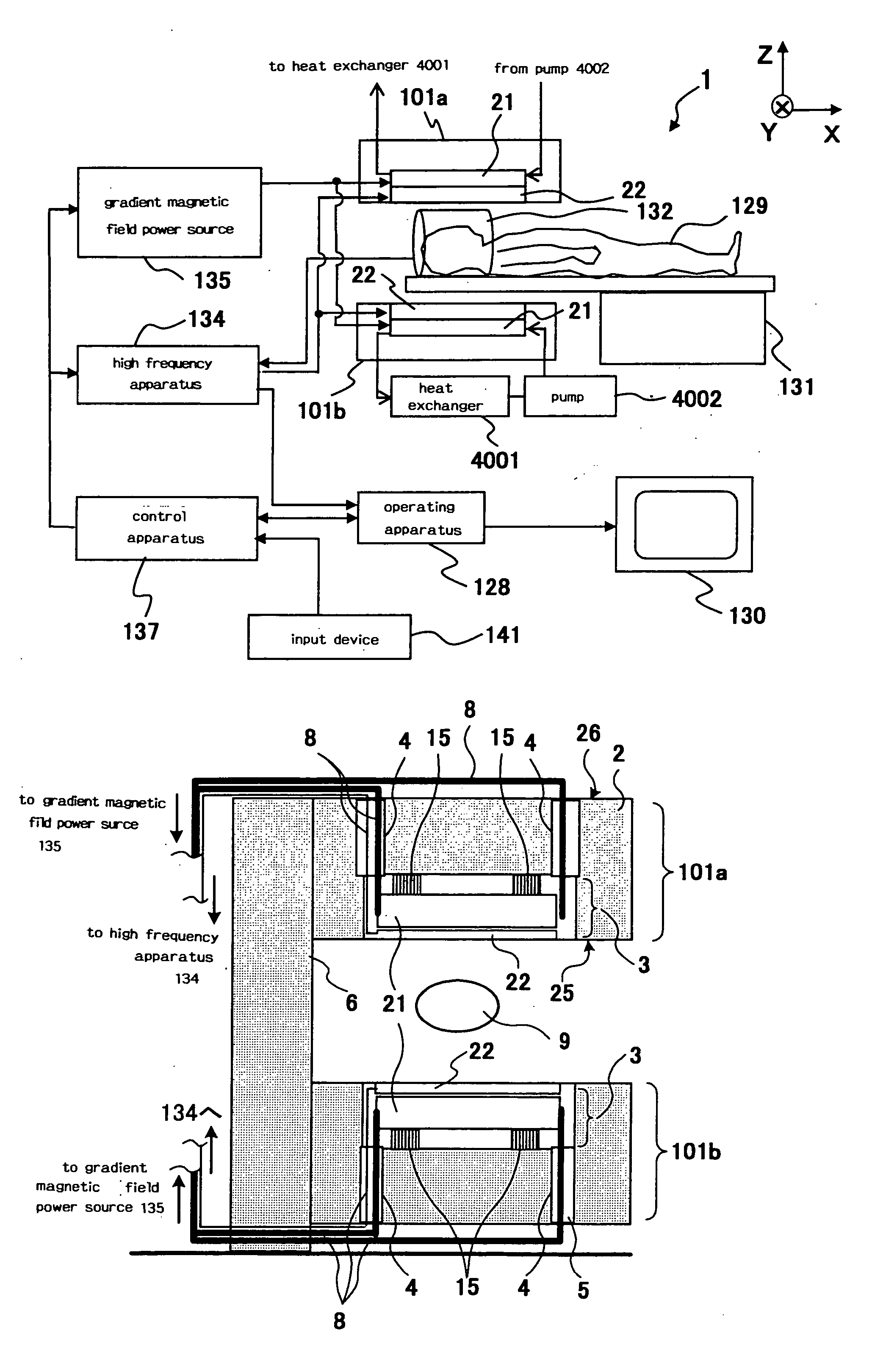
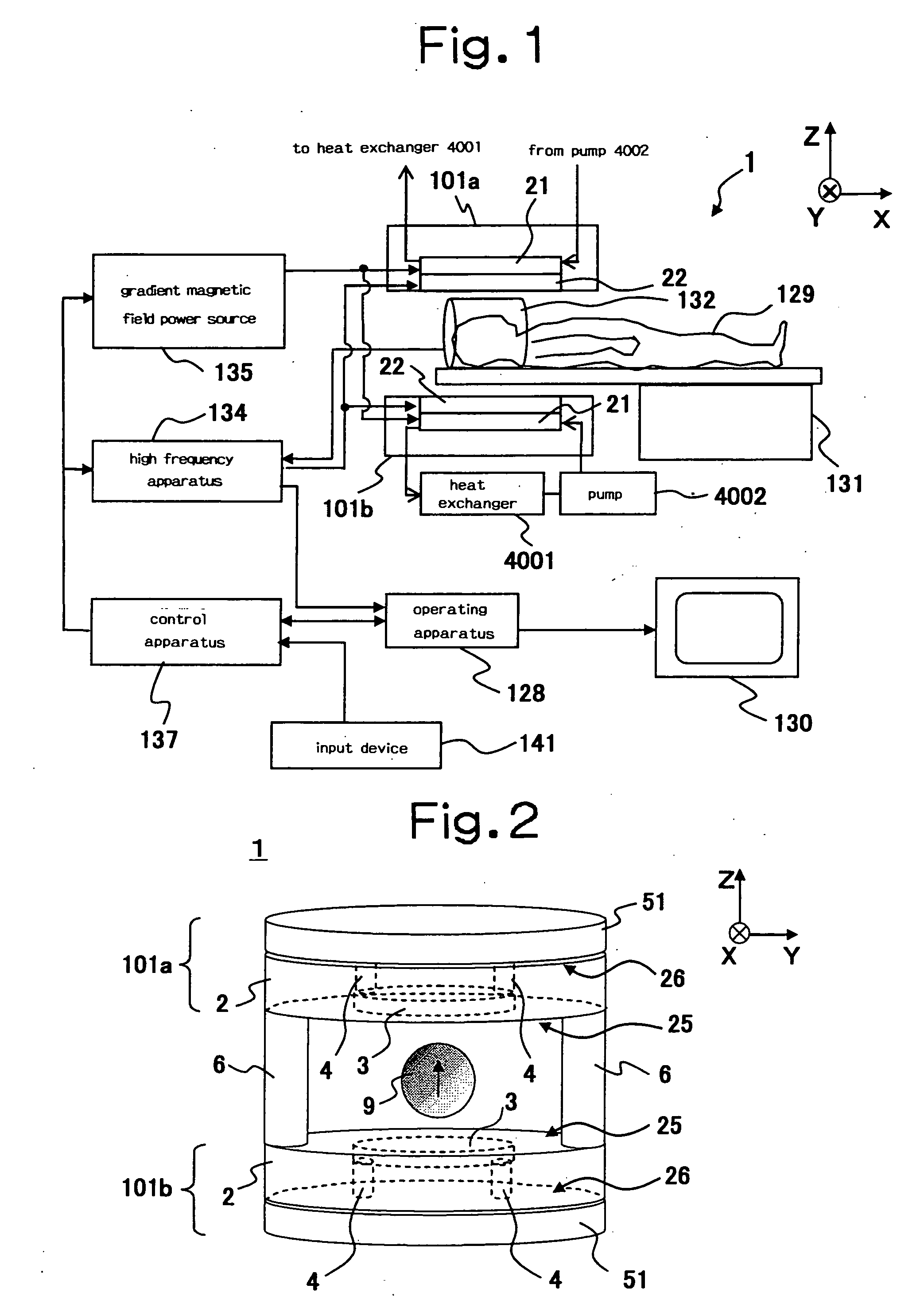
[0059] The MRI apparatus according to the first embodiment comprises, as a whole view thereof is shown in FIGS. 1 and 33, a static magnetic field generating apparatus 1, a gradient magnetic field coil 21, a high frequency irradiating coil 22, a bed 131 on which a subject 129 is laid, and a high frequency receiving coil 132. Besides these, the apparatus includes a gradient magnetic field power source 135, a high frequency apparatus 134, a control apparatus 137, an operating apparatus 128, an input device 141 and a display 130 as control and operation systems. Moreover, as shown in FIG. 1, the apparatus also comprises a heat exchanger 4001 and a pump 4002, which supply a refrigerant such as cooling water to the gradient magnetic field coil 21.
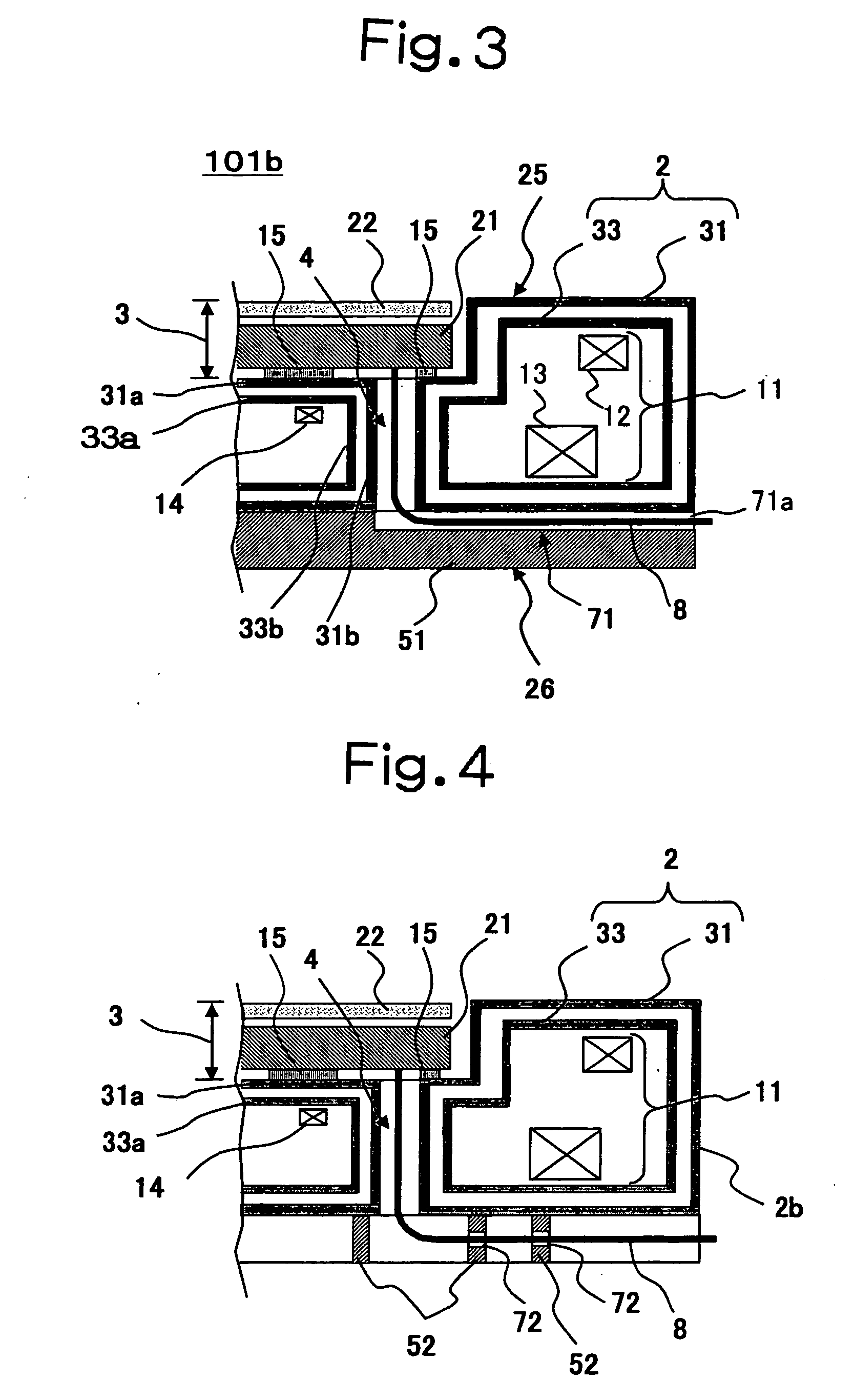
[0060] The static magnetic field generating apparatus 1 comprises, as shown in FIGS. 2, 3 and 33, a pair of superconducting magnets 101a and 10b, which are opposingly disposed on the upper side and lower side, and two of connecting columns 6 con...
second embodiment
[0080] The MRI apparatus according to the second embodiment of the present invention will be explained by referring to FIGS. 4, 5 (a) and (b). The MRI apparatus according to the second embodiment uses a grid reinforcing member 52 as a reinforcing member fixed to the cryostat 2 instead of the thick plate reinforcing member 51 used in the first embodiment. The other structure is the same as that of the first embodiment. By using the grid reinforcing member 52, it is possible to further reduce the weight compared with the case of using the thick plate reinforcing member 51 while enhancing the rigidity of the cryostat 2. Further, by providing the through-hole 4 at a position corresponding to an opening of the grid, the cables 8 or cooling pipes can be drawn out to the back surface side without providing through-holes in the grid reinforcing member 52. Further, even when the cables 8 etc. are drawn out to the outer peripheral surface side of the grid reinforcing member 52, it is sufficie...
third embodiment
[0081] The MRI apparatus of the third embodiment will be explained by referring to FIG. 6. Although the MRI apparatus of the third embodiment uses a thick plate reinforcing member 51 as a reinforcing member like the first embodiment, a thick plate reinforcing member 51 consisting of a plurality of separate members is used. In the example shown in FIG. 5, the circular thick plate reinforcing member 51 is divided into two of members 51a and 51b in a semicircular shape beforehand, and the members 51a and 51b are disposed so that a gap 73 should be secured between them and the opening of the through-hole 4 of the cryostat 2 should locate between them. The gap 73 can be thereby used as a pathway for disposing the cables 8 or cooling pipes. Therefore, it is not necessary to form a through-hole 71 like the thick plate reinforcing member 51 shown in FIG. 3, resulting in an advantage that manufacture of the thick plate reinforcing member 51 becomes easy.
[0082] In the example shown in FIG. 6...
PUM
 Abstract
Description
Claims
Application Information
 - R&D
- Intellectual Property
- Life Sciences
- Materials
- Tech Scout
- Unparalleled Data Quality
- Higher Quality Content
- 60% Fewer Hallucinations
Browse by: Latest US Patents, China's latest patents, Technical Efficacy Thesaurus, Application Domain, Technology Topic, Popular Technical Reports.
© 2025 PatSnap. All rights reserved.Legal|Privacy policy|Modern Slavery Act Transparency Statement|Sitemap|About US| Contact US: help@patsnap.com


