OFDM receiving method of OFDM receiver

a receiver and receiving method technology, applied in the direction of orthogonal multiplex, multiplex communication, digital transmission, etc., can solve the problems of phase error in subcarrier signals, demodulation errors, and the possibility of significant error in estimation results, so as to accurately estimate transmission paths

Inactive Publication Date: 2006-10-05
PANASONIC CORP
View PDF4 Cites 70 Cited by
  • Summary
  • Abstract
  • Description
  • Claims
  • Application Information

AI Technical Summary

Benefits of technology

[0017] Therefore, an object of the present invention is to provide an OFDM receiving method and an OFDM receiver capable of demodulating carriers without errors while accurately estimating the transmission paths even when realizing multiplexed communications between a transmitter and a receiver via a plurality of paths obtained by space division.
[0024] In the present invention, a pilot carrier is weighted by the reliability of the inverse matrix of the propagation coefficient. Thus, it is possible to suppress the estimation error due to noise emphasis, and to accurately detect the transmitter-receiver error. Separated data carriers are corrected based on the instantaneous variation of the detected transmitter-receiver error. Thus, it is possible to reduce the demodulation error. The inverse matrix is obtained after correcting the estimated propagation coefficient based on the temporal variation of the detected transmitter-receiver error. Thus, it is possible to follow the variations in the propagation path and to improve the precision of the signal separation by the inverse matrix multiplication. Moreover, a replica signal is produced by using the corrected propagation coefficient, whereby it is possible to correct the error at once for all stages, which needs to be done in a repetitive decoding process.

Problems solved by technology

If a synchronization estimation error occurs, there will be a phase error in the subcarrier signals.
If the phase error increases, it causes a demodulation error.
However, simply combining OFDM modulation scheme with MIMO-based transmission path estimation, as in the MIMO-based OFDM receiver 220 disclosed in the above-specified patent document, poses problems as follows.
Therefore, if the phase error is obtained from the separated pilot carriers, the error in the estimation result may become significant due to the noise emphasis.
Thus, it is not possible to properly correct the phase of the separated data carriers, resulting in a demodulation error.
Therefore, the receiver will become complicated and large in size.

Method used


Image

  • OFDM receiving method of OFDM receiver
  • OFDM receiving method of OFDM receiver
  • OFDM receiving method of OFDM receiver

Examples


first embodiment

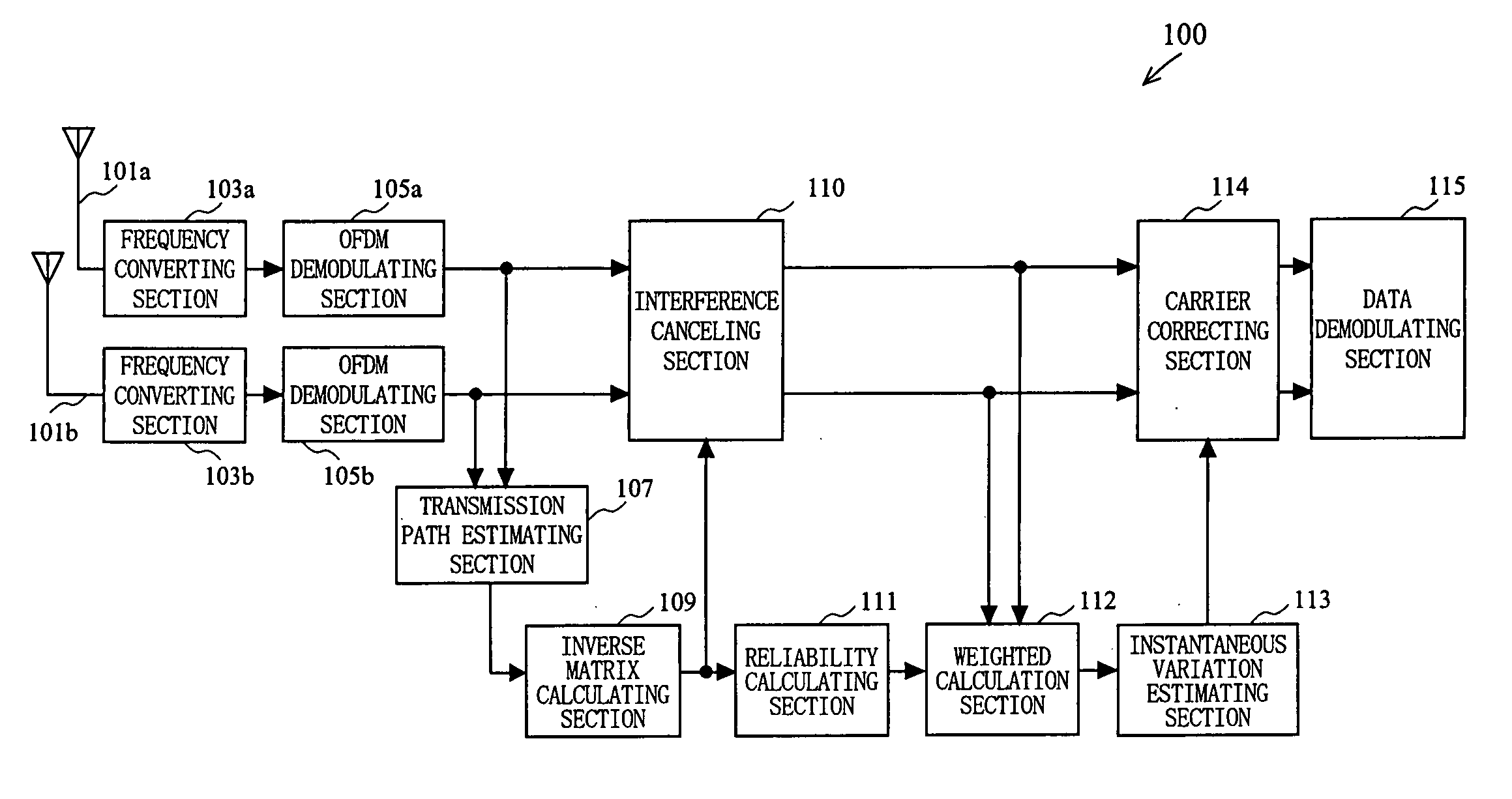
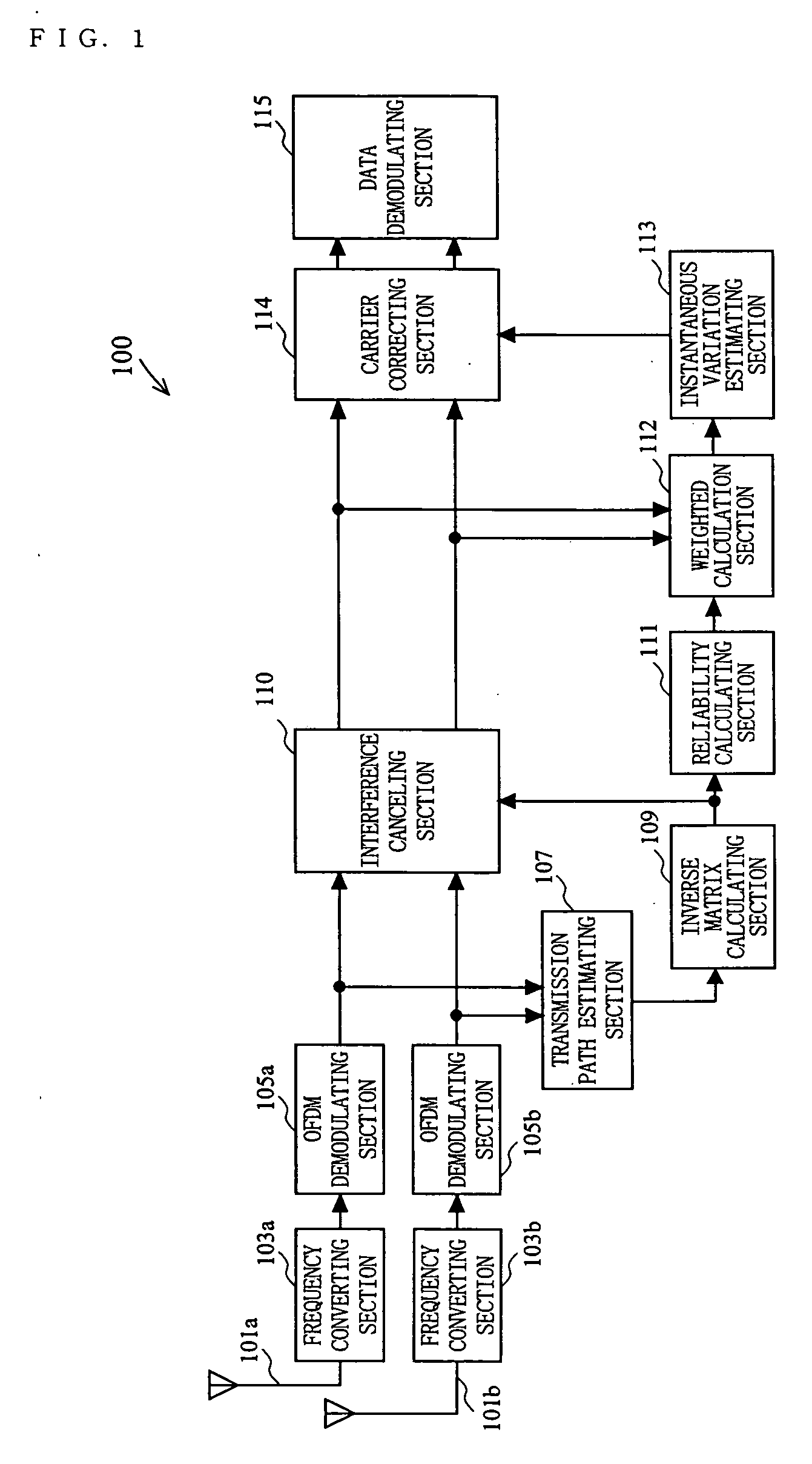
[0063]FIG. 1 is a block diagram showing a configuration of an OFDM receiver 100 according to a first embodiment of the present invention. Referring to FIG. 1, the OFDM receiver 100 of the first embodiment includes receiver antennas 101a and 101b, frequency converting sections 103a and 103b, OFDM demodulating sections 105a and 105b, a transmission path estimating section 107, an inverse matrix calculating section 109, an interference canceling section 110, a reliability calculating section 111, a weighted calculation section 112, an instantaneous variation estimating section 113, a carrier correcting section 114, and a data demodulating section 115.

[0064] The operation of various elements of the OFDM receiver 100 and the OFDM receiving method performed by the OFDM receiver 100 will now be described.

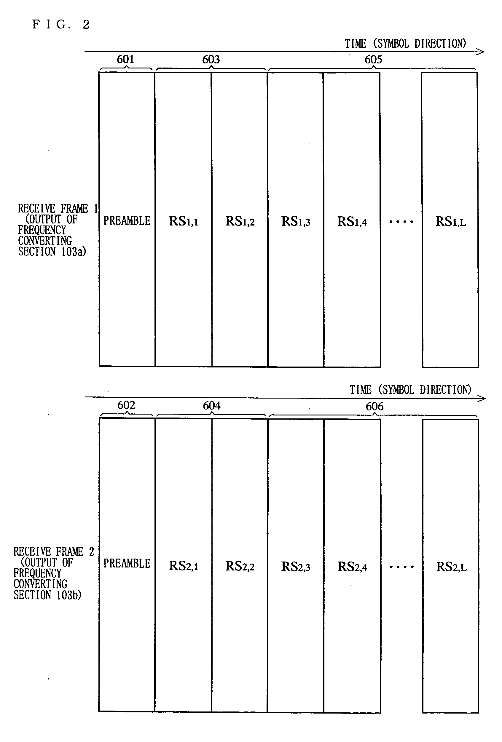
[0065] Signals transmitted from the OFDM transmitter (the transmit frame 1 and the transmit frame 2) are received at the receiver antennas 101a and 101b, and are inputted to the frequenc...

second embodiment

[0089]FIG. 12 is a block diagram showing a configuration of an OFDM receiver 120 according to a second embodiment of the present invention. Referring to FIG. 12, the OFDM receiver 120 of the second embodiment includes the receiver antennas 101a and 101b, the frequency converting sections 103a and 103b, the OFDM demodulating sections 105a and 105b, the transmission path estimating section 107, a propagation coefficient correcting section 128, the inverse matrix calculating section 109, the interference canceling section 110, the reliability calculating section 111, the weighted calculation section 112, a temporal variation estimating section 126, a frequency direction interpolation section 127, and the data demodulating section 115.

[0090] As shown in FIG. 12, the OFDM receiver 120 of the second embodiment includes the temporal variation estimating section 126, the frequency direction interpolation section 127 and the propagation coefficient correcting section 128, instead of the ins...

third embodiment

[0096]FIG. 15 is a block diagram showing a configuration of an OFDM receiver 130 according to a third embodiment of the present invention. Referring to FIG. 15, the OFDM receiver 130 of the third embodiment includes the receiver antennas 101a and 101b, the frequency converting sections 103a and 103b, the OFDM demodulating sections 105a and 105b, the transmission path estimating section 107, the propagation coefficient correcting section 128, the inverse matrix calculating section 109, the interference canceling section 110, the reliability calculating section 111, the weighted calculation section 112, the instantaneous variation estimating section 113, the carrier correcting section 114, the temporal variation estimating section 126, the frequency direction interpolation section 127, and the data demodulating section 115.

[0097] The OFDM receiver 130 of the third embodiment includes both the configuration for correcting the instantaneous variation component ea as described above in ...


PUM


Abstract

OFDM signals each including a plurality of subcarriers (including data carriers and pilot carriers) orthogonal to each other are received by a plurality of receiver antennas. The received OFDM signals are each OFDM-demodulated into a plurality of receive subcarriers. Based on the plurality of receive subcarriers, the propagation coefficients of a plurality of space paths are estimated. An inverse matrix of a propagation matrix whose elements are the estimated propagation coefficients is calculated. Interference cancellation is performed for the plurality of receive subcarriers by using the inverse matrix, and transmit subcarriers multiplexed in space are estimated. A reliability of the inverse matrix is calculated. A pilot carrier is extracted from the estimated transmit subcarriers, and the extracted pilot carrier is weighted according to the reliability. An error included in the plurality of receive subcarriers is corrected based on the weighted pilot carrier.

Description

BACKGROUND OF THE INVENTION [0001] 1. Field of the Invention [0002] The present invention relates to an OFDM receiving method and an OFDM receiver, for realizing multiplexed communications between a transmitter and a receiver via a plurality of paths obtained by space division. [0003] 2. Description of the Background Art [0004] In recent years, an OFDM (Orthogonal Frequency Division Multiplexing) modulation scheme, being a type of a multi-carrier transmission scheme, has been employed for wireless LAN, and the like, as a modulation scheme with a high resistance to frequency selective fading, which occurs under a multi-path environment in mobile communications. In an attempt to further improve the frequency efficiency, methods have been proposed in the art, which use a plurality of transmitter antennas and a plurality of receiver antennas to form MIMO (Multi Input Multi Output) channels, thereby realizing multiplexed communications between a transmitter and a receiver via a plurality...

Claims


Application Information

Patent Timeline
Patent Type & Authority Applications(United States)
IPC IPC(8): H04J11/00
CPCH04B7/0848H04L1/0048H04L1/06H04L5/026H04L25/03159H04L27/2657H04L27/2675H04L2025/03426H04L2027/003H04L2027/0048H04L2027/0067H04L2027/0087H04L2025/03414
Inventor SHIRAKATA, NAGANORITANAKA, KOICHIROHOSOKAWA, SHUYA
Owner PANASONIC CORP
Why Eureka
Try Eureka