Battery pack and cordless power tool having the same

Active Publication Date: 2006-10-05
HITACHI KOKI CO LTD
View PDF39 Cites 114 Cited by
  • Summary
  • Abstract
  • Description
  • Claims
  • Application Information

AI Technical Summary

Benefits of technology

[0010] It is therefore, an object of the present invention is to provide a cordless power tool capable of avoiding overheating to a switching element, thereby avoiding degradation of the lithium bat

Problems solved by technology

However, a new drawback will be found by the present inventors if FET is disposed at an electrical current path between the battery cell group and the DC motor.
Particularly, if the end tool bites or digs into a workpiece during operation, motor locking occurs so that excessive load cur

Method used


Image

  • Battery pack and cordless power tool having the same
  • Battery pack and cordless power tool having the same
  • Battery pack and cordless power tool having the same

Examples


first embodiment

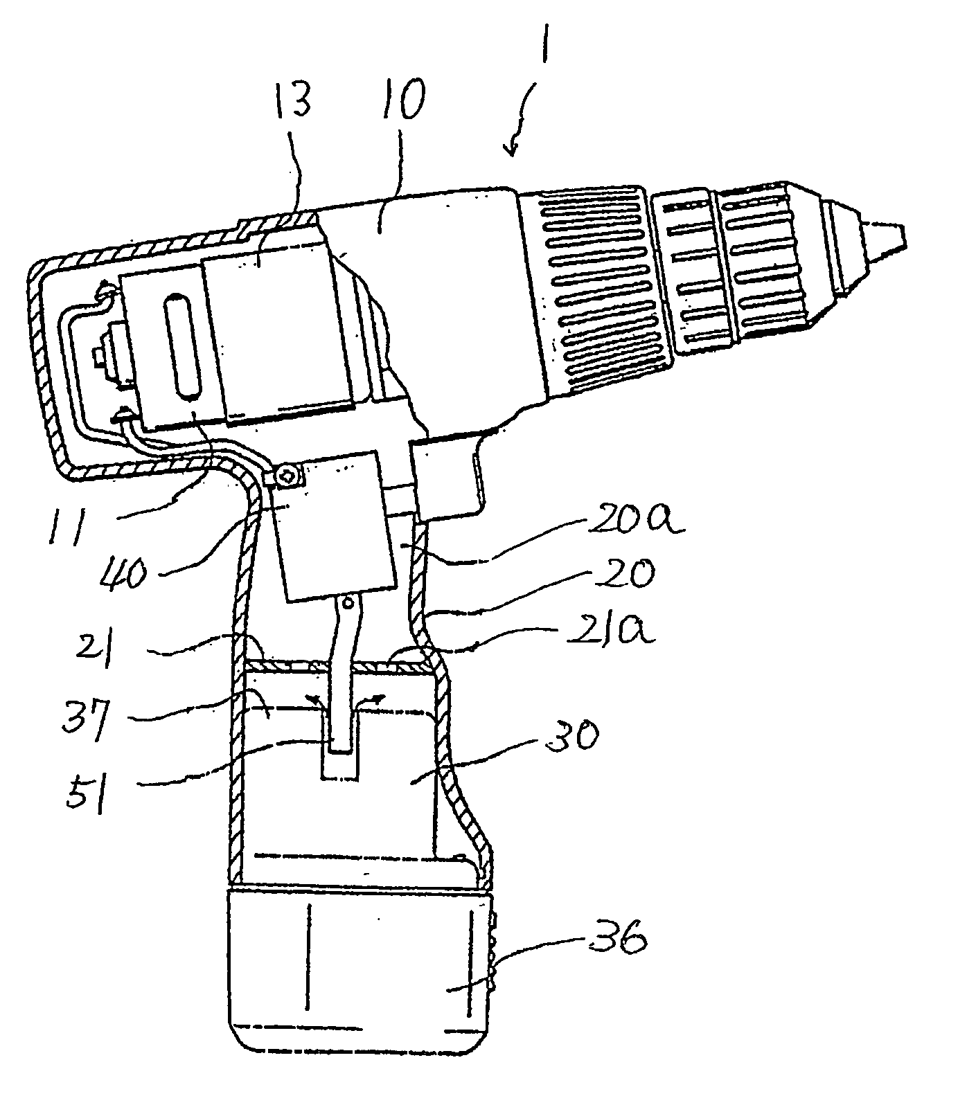
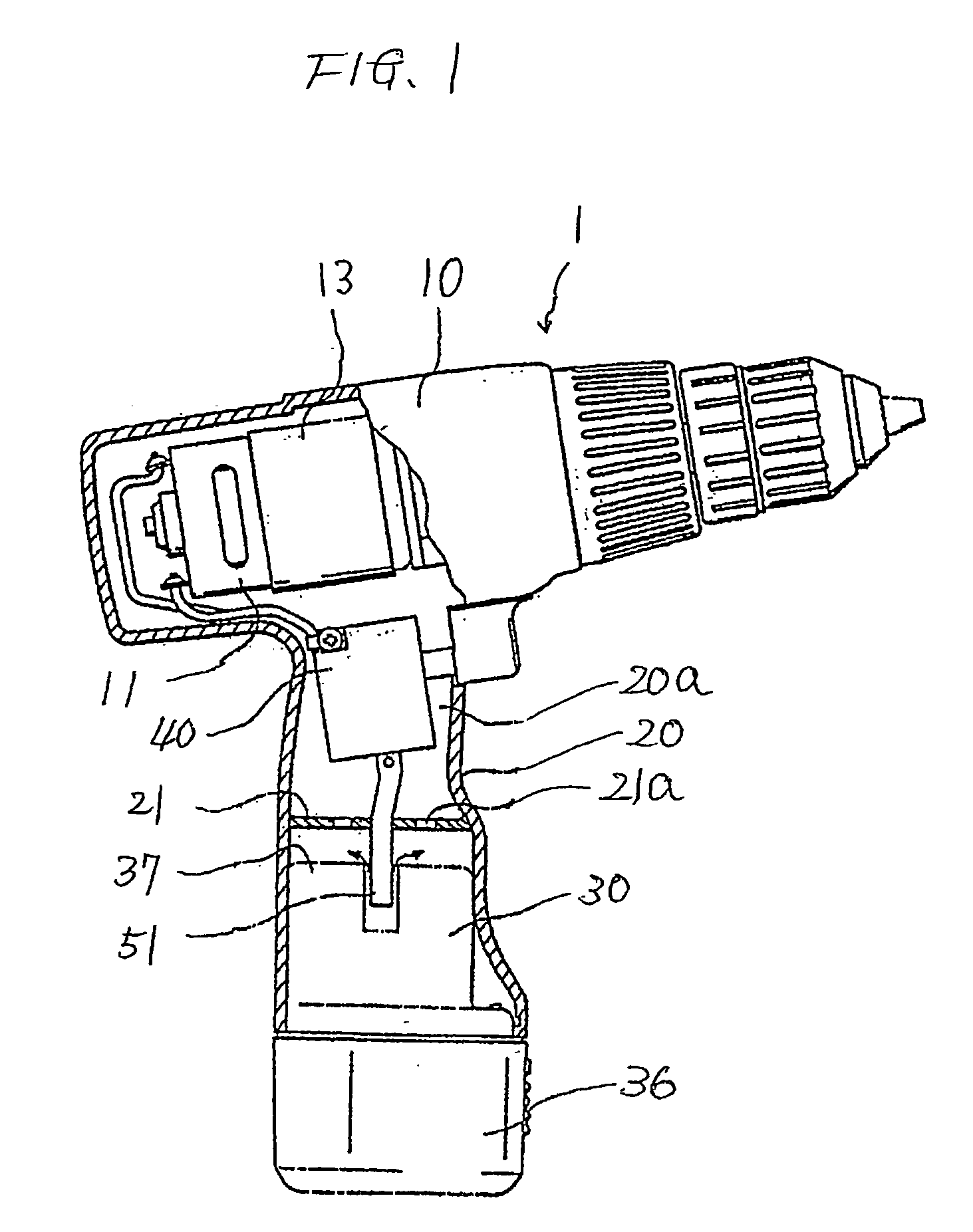
[0034] A cordless power tool having a battery pack according to the present invention will be described with reference to FIGS. 1 through 5. A portable fastener driver, a drilling machine, an impact drilling machine and a power wrench are examples of a cordless power tool. The power tool 1 includes a main barrel portion or a housing 10 and a handle portion 20 extending therefrom. The housing 10 has an internal housing space, and the handle portion 20 has an internal handle space in communication with the housing space.

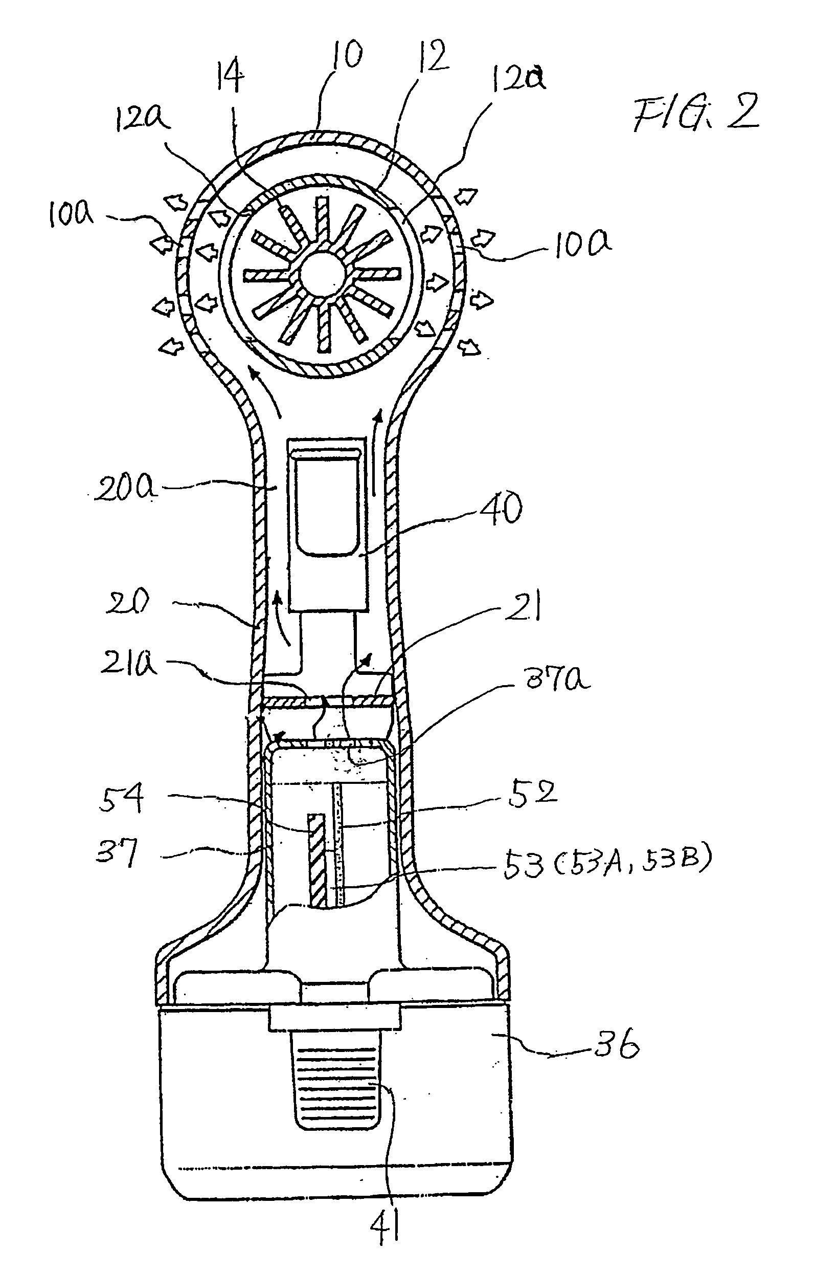
[0035] A battery pack 30 accommodating therein a group 31 of lithium battery cells including lithium battery cells 32 through 35 is attachable to a free end portion of the handle portion 20. The housing 10 is formed with a plurality of vent holes 10a at diametrically opposite sides thereof as shown in FIG. 2.

[0036] Within the housing 10, a DC motor 11 serving as a drive source is provided. The DC motor 11 has a motor housing 12 formed with vent holes 12a at diametrica...

second embodiment

[0077] Next, a battery pack according to the present invention will be described with reference to FIGS. 6(a) through 7.

[0078] A power tool 101 includes a handle portion 101a and a drive mechanism installing portion 101b in which a motor and a deceleration mechanism connected to a drive shaft of the motor are accommodated. The handle portion 101a defines an internal space in which a battery pack 110 is assembled. The internal space has an engagement region (not shown).

[0079] The battery pack 110 includes an insertion portion 111 and an accommodation portion 112 provided integrally with the insertion portion 111. The insertion portion 111 is to be inserted into the internal space of the handle portion 101a and has a configuration in conformance with the shape of the internal space. A protection board 114 having a protection circuit 200 (FIG. 7) is accommodated in the insertion portion 111. The protection circuit 200 is particularly required in case of the employment of lithium batte...


PUM


Abstract

A compact battery pack with high handling ability and restraining degradation of battery cells. The battery pack includes an insertion portion to be inserted into a handle portion of a cordless power tool and an accommodation portion in which all battery cells are accommodatable. A protection board with a protection circuit that protects batteries against overcharge and over-discharge is installed in the insertion portion. A switching element is connected between the battery cells and a drive motor of the power tool. An air passage in communication with the battery pack is formed within the handle and a main housing of the cordless power tool. The switching element is positioned at the air passage.

Description

BACKGROUND OF THE INVENTION [0001] The present invention relates to a battery pack for a cordless power tool, and more particularly, to a battery pack that stores rechargeable or secondary lithium battery cells. The present invention also relates to a cordless power tool having the battery pack. [0002] In a cordless power tool such as a driver, a drill, and an impact tool, rotation of a motor is decelerated by a deceleration mechanism, and the decelerated rotation is transmitted to an end tool. Conventionally, a commercial power source (alternating current source) is used as a power source to the motor. However recently, rechargeable alkaline batteries such as nickel-cadmium battery cells and nickel hydride battery cells are used as a power source of a cordless power tool. [0003] In accordance with an increase in a required voltage in the cordless power tool, the number of battery cells to be accommodated in a battery pack is increased. For example, since a nominal voltage of nickel...

Claims


Application Information

Patent Timeline
IPC IPC(8): H01M2/10H01M2/12
CPCH01M2/1055H01M10/052H01M10/425H01M10/482H01M10/5004B25F5/008H01M10/503H01M10/5067H02J7/0031Y02E60/122H01M10/5012H01M10/6563H01M10/643H01M10/623H01M10/613H02J7/00309Y02E60/10H01M50/213
Inventor ARADACHI, TAKAOTAKANO, NOBUHIRONISHIKAWA, TOMOMASAHANAWA, HIROYUKIOGURA, MASAYUKIFUNABASHI, KAZUHIKO
Owner HITACHI KOKI CO LTD
Why Eureka
Try Eureka