Device for moving die tools and moulds in a press

a technology of press and tool, which is applied in the direction of metal-working holders, positioning apparatuses, supports, etc., can solve the problems of increasing the floor area required for each press, requiring manual force or special gripping devices, and occupying considerable space in the area, so as to reduce friction between the strip and the bar, reduce the friction, and reduce the effect of wear and friction

Inactive Publication Date: 2006-10-05
HEDIN LAGAN
View PDF16 Cites 15 Cited by
  • Summary
  • Abstract
  • Description
  • Claims
  • Application Information

AI Technical Summary

Benefits of technology

[0010] Preferably the gear wheel is covered by a housing. The housing, which preferably opens only in the direct of the bar, protects the gear wheel from damage caused by the objects on the table of the press. Further, operators working close to the machine are also protected from injuries caused by the gear wheel.
[0011] Preferably the gear wheel and a vertical shaft, by which the motor is able to rotate the gear wheel, are mounted adjacent to a lateral side of the press table. An advantage of this is that it provides a particularly compact design.
[0012] According to a preferred embodiment the bar is provided with the gear teeth on at least one lateral side, the gear wheel being adapted to rotate in a substantially horizontal plane. An advantage of this embodiment is that the gear teeth are not located at the upper surface and not in direct contact with the strip. The provision of the gear teeth on a lateral side provides for minimum wear and friction related to the gear teeth.
[0013] Preferably said bag is inflated by means of pressurized air. Inflating with pressurized air provides for a simple control of the force with which the bar lifts the object located on the table.
[0014] According to a preferred embodiment the device further comprises at least one rail unit, the rail unit comprising a rail being vertically movable in a rail slot in the upper surface of the table, said rail slot being parallel with and adjacent to said slot housing said bar, the rail unit further comprising a rail bag located at the bottom of the rail slot, and a number of rollers supported by the rail, the rail being vertically movable, by means of inflating the rail bag, from a first position, in which the rollers are located below the upper surface of the table, to a second position, in which the rollers extend above the upper surface of the table to lift objects located on the table, the rail being adapted to be moved to its second position at the same time as the bar is moved to its second position in order to decrease the pressure of the objects on said bar and to decrease the friction between said bar and said strip. The rail unit provides for assisting the bar in lifting the object / -s from the upper surface of the press table. Thus the friction between the strip and the bar is decreased, which lowers the power needed to move the object / -s.
[0015] A further object of the present invention is to provide a table for a press, which table enables easy moving of die tools and moulds without requiring a lot of floor space.

Problems solved by technology

A problem with the die transfer system of U.S. Pat. No. 4,691,554 is, however, that manual force or a special gripping device is required to move the die.
A problem with this bar solution is, however, that it takes up considerable space in the area of the press and increases the demand for floor area required for each press.

Method used


Image

  • Device for moving die tools and moulds in a press
  • Device for moving die tools and moulds in a press
  • Device for moving die tools and moulds in a press

Examples


Embodiment Construction

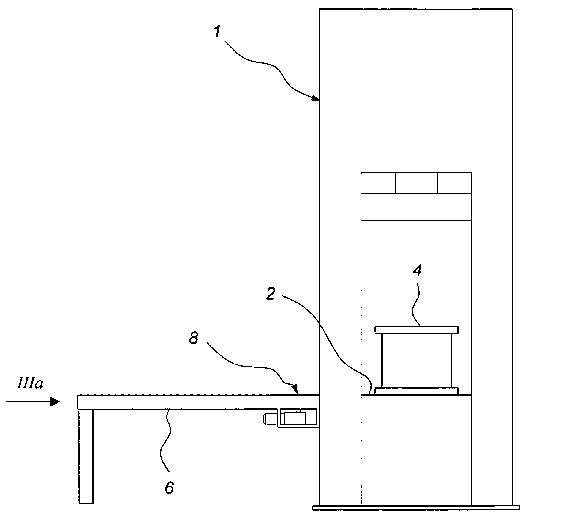
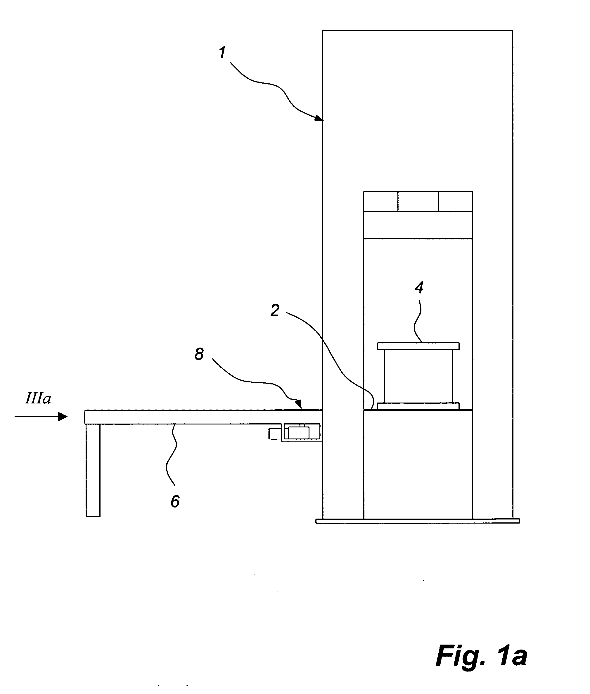
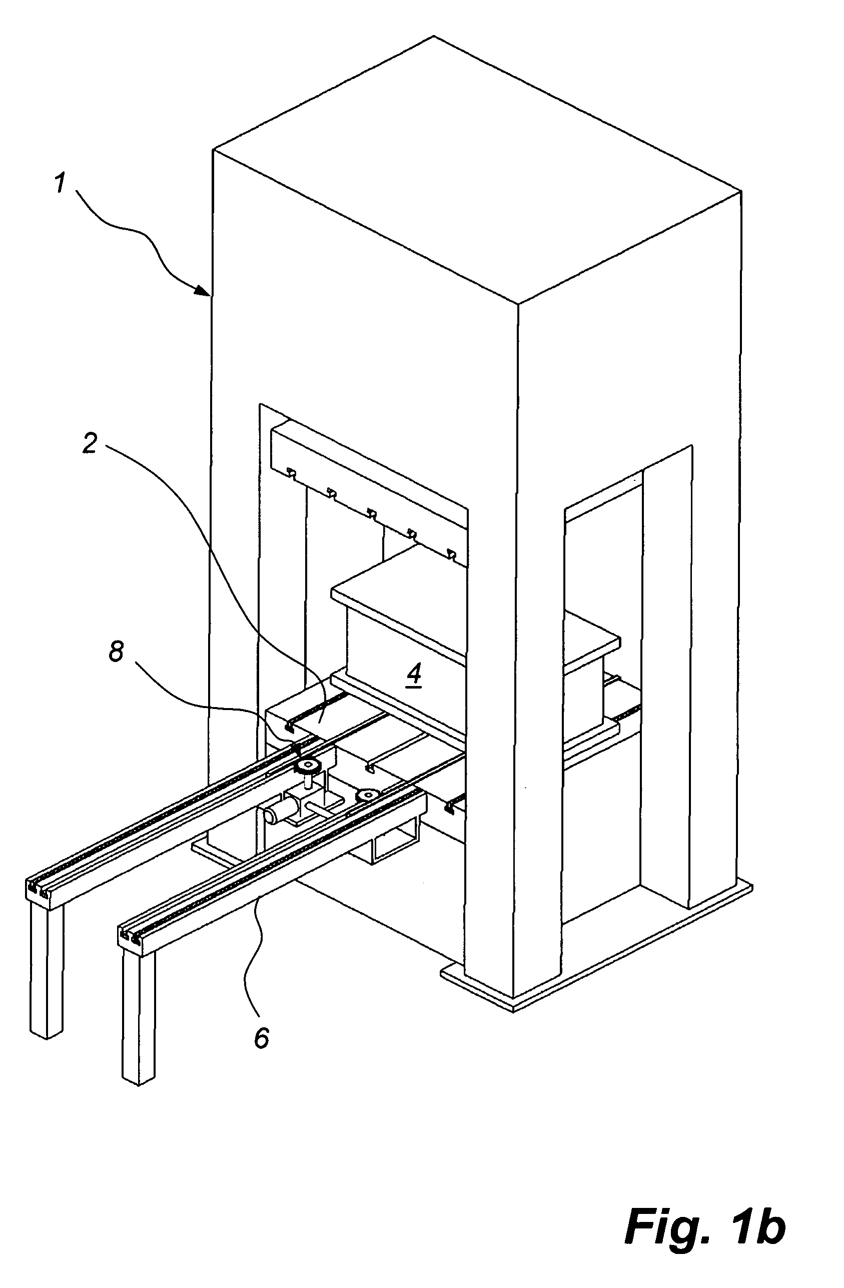
[0033]FIGS. 1a and 1b show a press 1. The press comprises a press table 2, which may also be called a bolster, which is located at the lower part of the press 1. On the press table 2 a heavy object 4 is located. The object 4 is typically a die tool or a mould on which the press 1 has just performed a pressing operation. Due to the weight of the object 4, typically 300-10 000 kg it is not easily moved away from the press 1. Adjacent to the press 1 a side table 6 is located. The side table 6 is an example of an intermediate storage place for objects like die tools and moulds. The press is provided with a device 8 for moving the object 4.

[0034]FIGS. 2a and 2b show the press 1 after the device 8 has moved the object 4 from the press table 2 to the side table 6.

[0035]FIG. 3a-c show the device 8 in closer detail. The device 8 comprises a bag 10 located at the bottom 12 of an elongated inverted T-slot 14 formed in an upper surface 16 of the press table 2. The inverted T-slot 14 is prefer...


PUM

PropertyMeasurementUnit
weightaaaaaaaaaa
pressureaaaaaaaaaa
shapeaaaaaaaaaa

Abstract

A device for moving objects ( 4 ) to and from the table ( 2 ) of a press ( 1 ) comprises a bar ( 24 ) being vertically movable, by means of inflating a bag ( 10 ), from a first position in which an upper surface ( 26 ) of the bar ( 24 ) is located below the upper surface ( 16 ) of the table ( 2 ) to a second position in which the upper surface ( 26 ) of the bar ( 24 ) is located above the upper surface ( 16 ) of the table ( 2 ). The bar ( 24 ) is adapted to slide horizontally in its longitudinal direction and is provided with gear teeth ( 28 ). A gear wheel ( 32 ), engaging the gear teeth ( 28 ) of the bar ( 24 ), is adapted to move the bar ( 24 ) in the horizontal direction along the slot ( 14 ) when the bar ( 24 ) is in its second position and thus to move an object ( 4 ) resting on the upper surface ( 26 ) of the bar ( 24 ).

Description

FIELD OF THE INVENTION [0001] The present invention relates to a device for moving objects to and from the table of a press, said device comprising a bag located at the bottom of an elongated slot formed in an upper surface of the table, a strip located in the slot on top of the bag, and an elongated bar which is located in the slot on top of the strip, the bar being vertically movable, by means of inflating the bag, from a first position in which an upper surface of the bar is located below the upper surface of the table to a second position in which the upper surface of the bar is located above the upper surface of the table so as to lift an object located on the table, the bar being adapted to slide horizontally in its longitudinal direction on top of the strip. BACKGROUND OF THE INVENTION [0002] In presses die tools and moulds need to be moved in and out of a press table on a regular basis. U.S. Pat. No. 4,691,554 describes a die transfer system which is based on vertically mova...

Claims


Application Information

Patent Timeline
Patent Type & Authority Applications(United States)
IPC IPC(8): B23Q3/155
CPCB30B15/028Y10T483/1729Y10S100/918
Inventor HEDIN, KENNETH
Owner HEDIN LAGAN
Why Eureka
Try Eureka