Shear system for an electric hair removing apparatus

a hair removal and electric technology, applied in the direction of metal working devices, etc., can solve the problems of wasting a lot of effort in obtaining a shave, and achieve the effects of high hair removal efficiency, gentle skin treatment, and high probability

Active Publication Date: 2006-10-12
BRAUN GMBH
View PDF21 Cites 20 Cited by
  • Summary
  • Abstract
  • Description
  • Claims
  • Application Information

AI Technical Summary

Benefits of technology

[0011] Preferred shear systems are highly effective in the removal of hair. In particular, long hair and / or hair resting flat against the skin are captured and removed by the preferred shear systems with a comparatively high degree of probability. Preferred shear systems generally enable a very short cut, meaning that the hair is severed very close to the skin surface.
[0012] The feeding device may include plural feeding elements arranged in correlation with the geometry of the outer cutter. These feeding elements are comprised of a plastics material preferably at least in a region provided for contact with the skin. This has the advantage of ensuring a very gentle treatment of the skin.
[0013] The feeding elements of the feeding device may be located laterally adjacent to the shearing unit. In this arrangement it is particularly advantageous for the feeding device to be in abutting engagement with the shearing unit laterally only in some areas. A small area of contact between the feeding device and the shearing unit enables friction to be maintained at a low level so that the additional power consumption for the drive unit of the feeding device is comparatively low.
[0014] The outer cutter may include bars and cutting apertures succeeding each other in alternation, with the feeding elements of the feeding device being arranged to precede the respective bars. This may have the advantage of enabling hair from the bar area to be fed to the cutting apertures by means of the feeding elements and to be likewise severed. The bars are in particular shaped in such manner that the cutting apertures widen from the side of the outer cutter where the undercutter is arranged toward the environment. This shaping facilitates the process of threadedly engaging the hairs with the cutting apertures. Furthermore it is advantageous for the bars to enclose an angle with a cutting edge of the undercutter. This enables edge-on-edge impact between the undercutter and the outer cutter to be avoided in addition to having a beneficial effect on the threading efficiency.
[0015] In a preferred embodiment the feeding device is moved parallel to a direction in which the bars and cutting apertures of the outer cutter succeed each other. In this arrangement the feeding device is preferably caused to perform an oscillatory motion. The frequency of the oscillatory motion of the feeding device may correspond in particular to the frequency of the relative motion between the outer cutter and the undercutter. The amplitude is preferably selected smaller than the amplitude of the relative motion between the outer cutter and the undercutter. Such a movement can be generated without major effort and allows an effective feeding of the hairs to the cutting apertures. Moreover, this motion is comparatively kind to the skin. To produce the motion provision may be made for a coupling mechanism to transmit the relative motion between the outer cutter and the undercutter to the feeding device.

Problems solved by technology

In constructing shear systems, considerable effort is sometimes expended to obtain a shave as thorough as possible.
One difficulty presenting itself in this connection is the reliable removal of hairs lying flat against the skin, and the art knows of shear systems which are equipped with structural elements specifically developed for this purpose.

Method used


Image

  • Shear system for an electric hair removing apparatus
  • Shear system for an electric hair removing apparatus
  • Shear system for an electric hair removing apparatus

Examples


Embodiment Construction

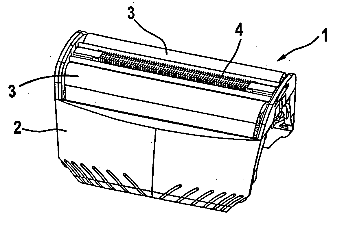
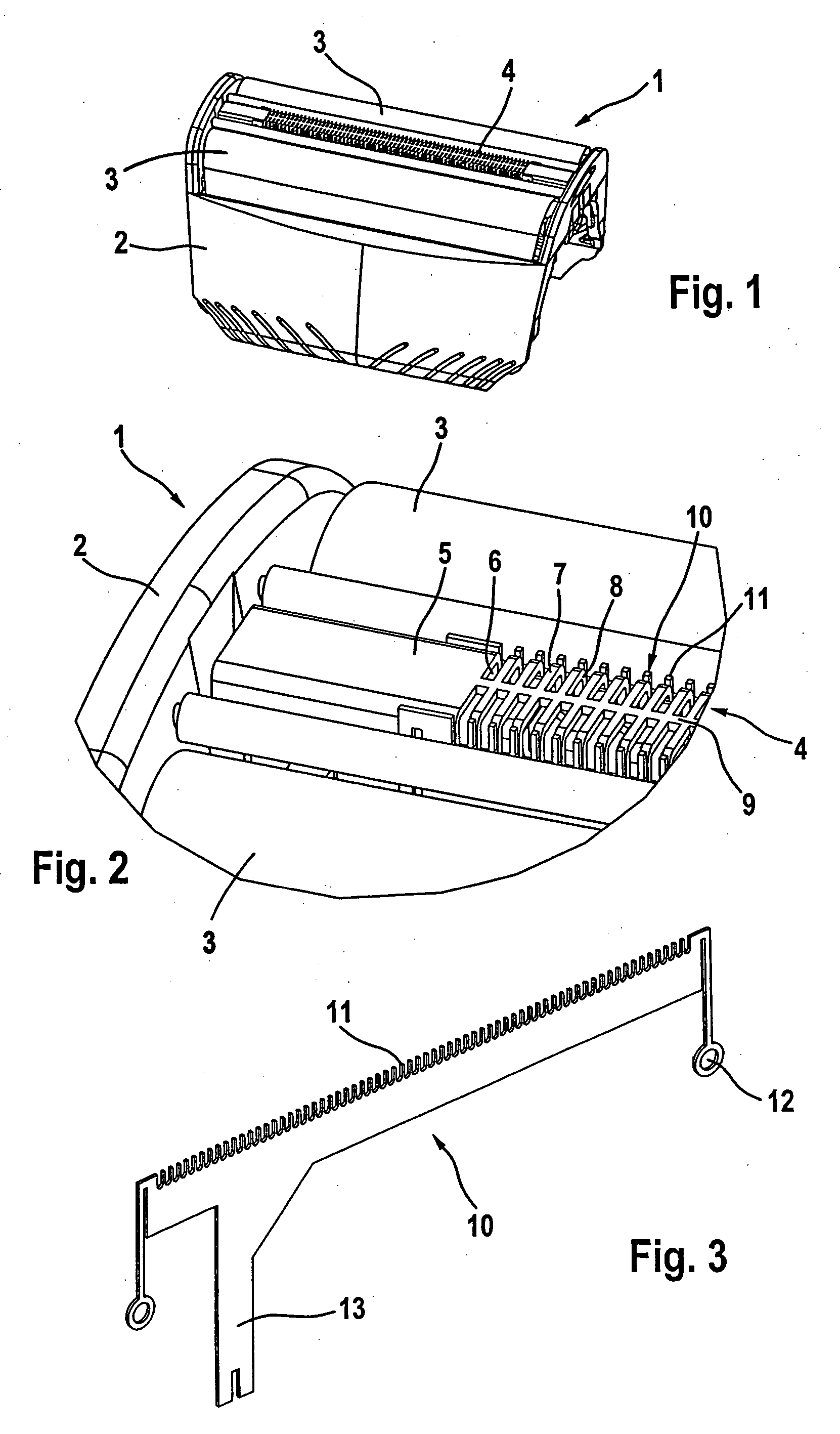
[0030]FIG. 1 shows a shaving head 1. An enlarged detail of FIG. 1 is shown in FIG. 2. The shaving head 1 has a casing part 2 and two shaving foils 3 arranged in spaced relation to each other. Interposed between the shaving foils 3 is a pre-cutter 4. The pre-cutter 4 serves to shorten comparatively long hairs and / or hairs lying flat against the skin so as to enable them to enter readily the perforations in the shaving foils 3. To accomplish this, the pre-cutter 4 is provided with a cutting comb 5 and a cutting blade 6 disposed within the cutting comb 5. The cutting comb 5 has a plurality of U-shaped parallel bars 7 separated from each other by intermediate slits 8 for entry of the hairs. A center bar 9 connects the bars 7 in the middle of the cutting comb 5. The cutting blade 6 performs an oscillatory linear motion relative to the cutting comb 5 in a direction transverse to the bars 7 of the cutting comb 5. This motion severs the hairs threaded into the slits 8 of the cutting comb 5....


PUM


Abstract

The invention is directed to a shear system for an electric hair removing apparatus, in particular for an electric shaving apparatus, including at least one shearing unit having an outer cutter and an undercutter that are set in relative motion. The shear system of the invention includes at least one feeding device arranged to precede the shearing unit and is characterized in that the feeding device is set in motion relative to the outer cutter.

Description

CROSS-REFERENCE TO RELATED APPLICATIONS [0001] This is a continuation of PCT Application No. PCT / EP2004 / 009824, filed on Sep. 3, 2004, which claims priority to German Patent Application No. 103 44 566.8, filed on Sep. 25, 2003, which is incorporated herein by reference in its entirety.TECHNICAL FIELD [0002] This invention relates to a shear system for an electric hair removing apparatus, in particular for an electric shaving apparatus. The invention relates further to a hair removing apparatus, in particular an electric shaving apparatus, comprising such a shear system. BACKGROUND [0003] Shear systems are employed in a wide variety of electric shaving devices. In constructing shear systems, considerable effort is sometimes expended to obtain a shave as thorough as possible. One difficulty presenting itself in this connection is the reliable removal of hairs lying flat against the skin, and the art knows of shear systems which are equipped with structural elements specifically develo...

Claims


Application Information

Patent Timeline
Patent Type & Authority Applications(United States)
IPC IPC(8): B26B19/12B26B19/04B26B19/10B26B19/38
CPCB26B19/042B26B19/3846B26B19/382B26B19/10
Inventor BADER, RAOULBURREL, LUISDALITZ, WERNERMOEHRING, ANDREASKLUGE, MARTINNAUBER, ANDRESCHAAF, UWE
Owner BRAUN GMBH
Why Eureka
Try Eureka