Pivoting sliding door for vehicles

a sliding door and vehicle technology, applied in the direction of doors, wing accessories, hinges, etc., can solve the problems of higher investment cost and unsatisfactory mechanism, and achieve the effect of higher investment cos

Inactive Publication Date: 2006-10-12
KNORR BREMSE GMBH
View PDF26 Cites 21 Cited by
  • Summary
  • Abstract
  • Description
  • Claims
  • Application Information

AI Technical Summary

Benefits of technology

[0007] The present disclosure includes a door drive that, independently of the momentary loading of the door wing, ensures an opening of the door in the event of an emergency via a door emergency operating device always under the same kinematic and mainly dynamic conditions. In the process, the pivoting sliding door of the present disclosure requires neither more space than the currently used over-dead-center mechanism, nor results in higher investment costs.

Problems solved by technology

Another issue is a result of the prerequisite that, in event of a power failure of the door drive, it is nevertheless ensured that the door is not opened by persons or objects striking against the door wing.
In this condition, even if mechanical locks are still present, it must not be possible to open the door by exercising force upon the door wing or by operating the door handle, but the door has to remain firmly and reliably closed.
As reliably as such devices prevent the unintentional or unauthorized opening of the doors, this mechanism is not desirable when the door is, in fact, to be opened by the door emergency operating device, particularly if this should take place by untrained persons and / or in the event of panic.
In the process, the pivoting sliding door of the present disclosure requires neither more space than the currently used over-dead-center mechanism, nor results in higher investment costs.

Method used


Image

  • Pivoting sliding door for vehicles
  • Pivoting sliding door for vehicles
  • Pivoting sliding door for vehicles

Examples


Embodiment Construction

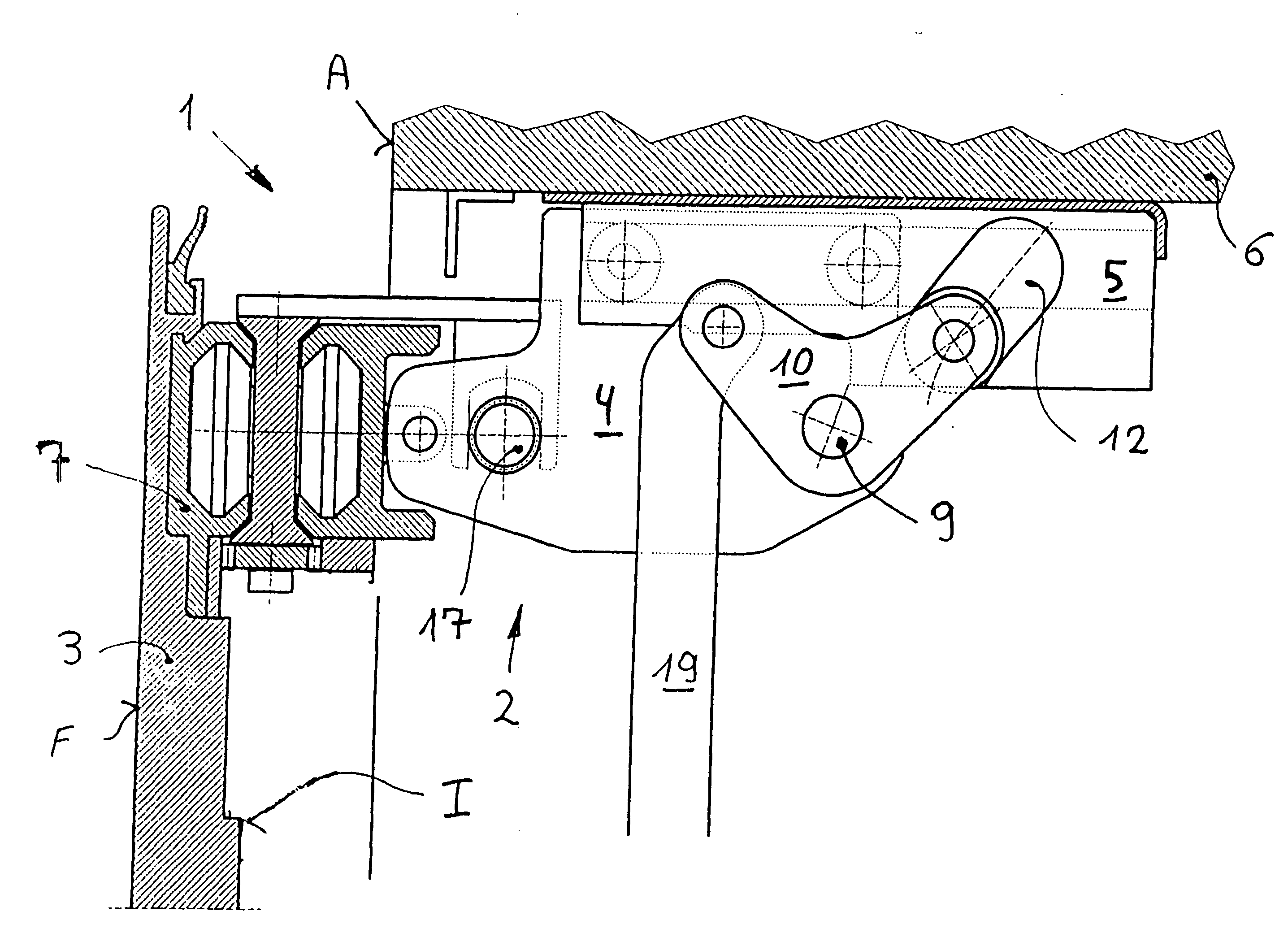
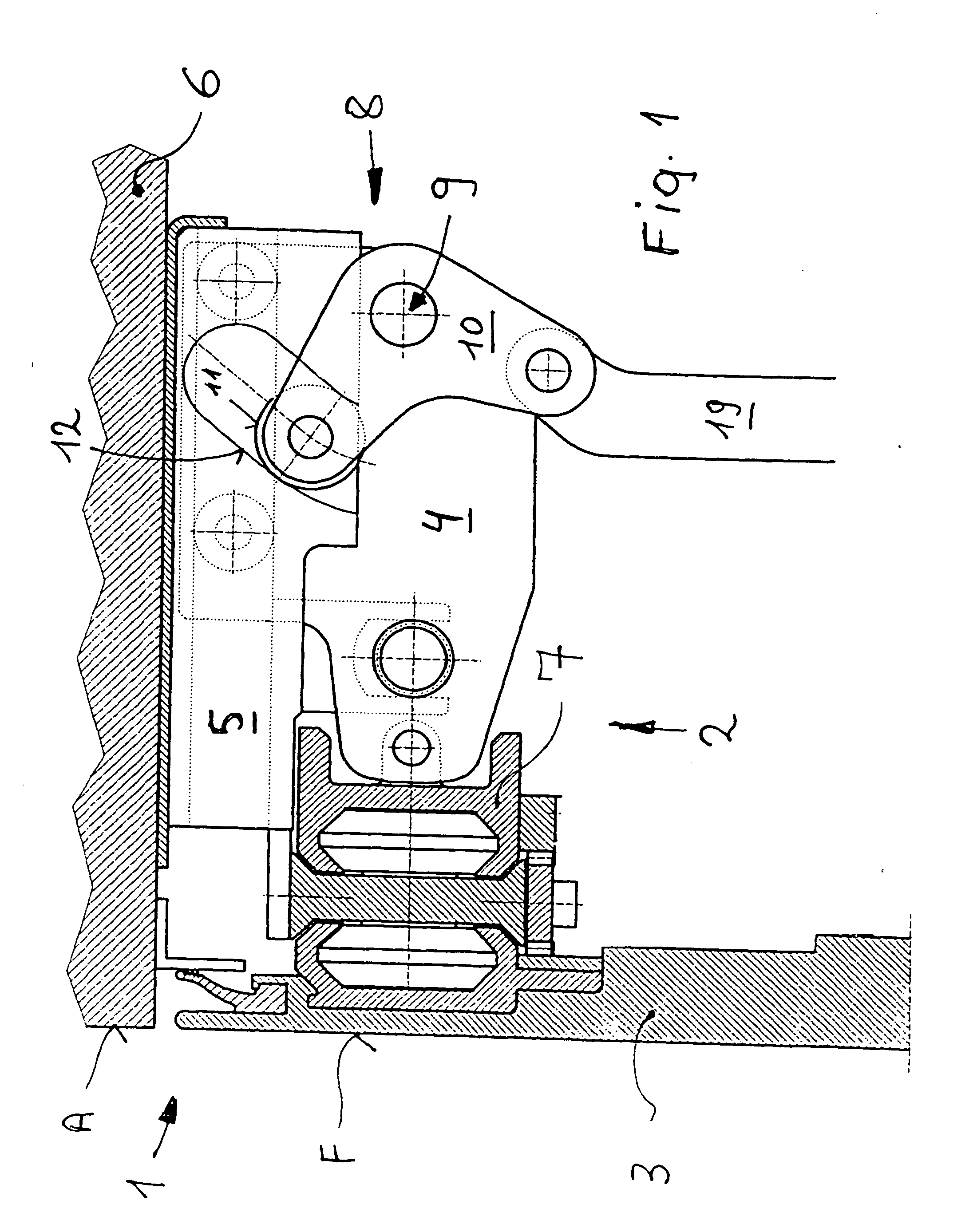
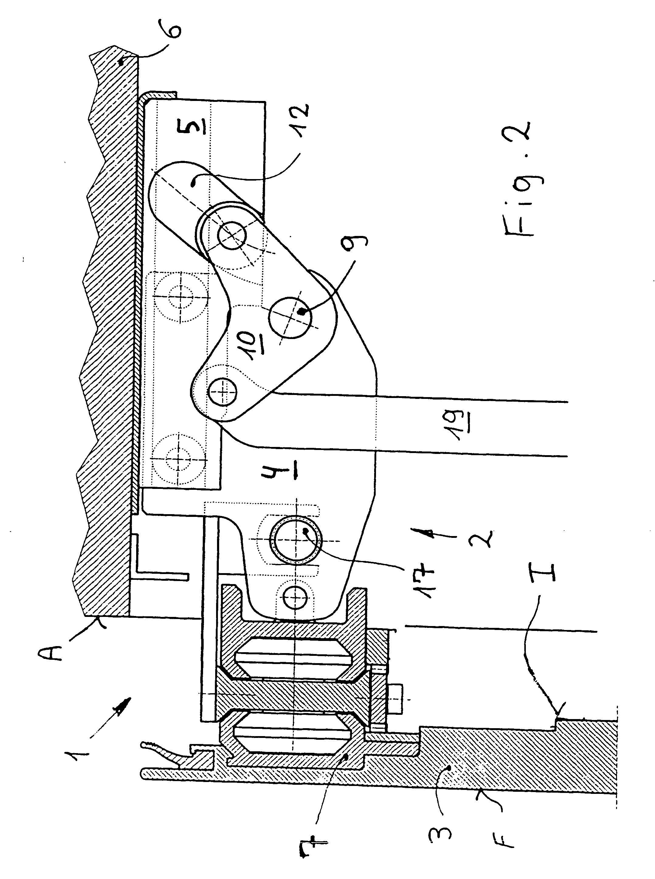
[0015]FIG. 1 shows an edge area of a door 1. In the case of conventional doors of vehicles, for example, rail vehicles, in which the doors are arranged in side walls of a vehicle body 6, this section therefore extends at least essentially normal with respect to the longitudinal vehicle axis. FIG. 1 shows an area of a door mechanism 2 which, together with at least one door wing 3, is arranged on a carriage 4 which is displaceable by rollers 11 in guides 5 which are fixedly fastened on the vehicle body 6, or on a portal or frame fixedly connected with the vehicle body 6.

[0016] In a closed position illustrated in FIG. 1, an exterior surface F of the door wing 3 corresponds essentially to an exterior surface A of the vehicle body 6, as may be customary in pivoting sliding doors. The illustrated embodiment shows a telescopable door. Here, a telescope 7, which may include at least three parts is, on one side, connected with the carriage 4, and on another side with the door wing 3. This p...


PUM


Abstract

The invention relates to a pivoting sliding door for vehicles, comprising a door wing (3), drive devices (2), transversal guiding devices (4, 5), and longitudinal guiding devices (7), which enable the at least one door wing (3) to move transversal to the vehicle wall and along the vehicle wall. The longitudinal guiding devices move in a transverse direction by means of the transversal guiding devices. When closed, the door is locked by a pivot part (10), which engages inside a guide (12) whereby preventing the door from being unintentionally opened. The invention is characterized in that the pivot part (10) has a guide part (11) that interacts with a guide (12) and that the guide, in the area in which the pivot part (10) interacts with the guide when the door is closed, has a circular arc section (12b) around the actual position of the rotation axis (9) of the pivot part (10).

Description

BACKGROUND AND SUMMARY [0001] The present disclosure relates to a pivoting sliding door for vehicles, particularly rail vehicles or lift cabins, having at least one door wing which, in a closed position, is arranged in a vehicle wall or body and which, in an opened position, is arranged on an exterior side in front of the vehicle wall or body and in the process leaves a door opening free. Driving devices as well as transversal guiding devices and longitudinal guiding devices are provided which permit a movement of the at least one door wing transversely to the vehicle wall or body and along the vehicle wall or body, the longitudinal guiding devices being moved by the transversal guiding devices. [0002] A door drive of this type is known, for example, from European Patent Document EP 0 820 889 A. In the case of this door drive as well as in the case of many other door drives, almost the entire driving device, which is mounted on a carriage, moves along with the transversal guiding de...

Claims


Application Information

Patent Timeline
Patent Type & Authority Applications(United States)
IPC IPC(8): E05D15/10B60J5/06E05F15/14
CPCB60J5/062E05F15/652E05D2015/1071E05D2015/1097E05Y2201/22E05Y2201/238E05Y2201/604E05Y2201/624E05Y2201/64E05Y2201/686E05Y2900/51E05Y2201/434E05Y2600/11E05Y2600/322E05Y2800/73E05D15/1068E05Y2201/608E05F15/655B60J5/06E05D11/00E05D15/1044E05Y2400/30E05F15/40
Inventor JAROLIM, REINHOLD
Owner KNORR BREMSE GMBH
Why Eureka
Try Eureka