Exhaust gas purification device of internal combustion engine

Inactive Publication Date: 2006-10-12
DENSO CORP
View PDF5 Cites 24 Cited by
  • Summary
  • Abstract
  • Description
  • Claims
  • Application Information

AI Technical Summary

Benefits of technology

[0013] The deposit amounts of the SOF and the soot as the particulate components are estimated separately. The temperature of the particulate filter is increased to execute the elimination treatment for eliminating the SOF from the particulate filter before the SOF deposit amount becomes excessive. Rapid combustion of the soot due to the combustion of the SOF is prevented to suppress an excessive increase of the particulate filter temperature. The soot deposit amount may be estimated from a relation to a p

Problems solved by technology

Therefore, in the case where a large amount of the SOF is deposited, there is a possibility that heat generated in the combustion of the SOF triggers rapid combustion of the soot even if exhaust gas temperature is low.
As a result, a filter substrate or a catalyst is damaged if the temperature of the particulate filter is increased to high temperature over allowable limit temperature.
Therefore, it is difficult to estimate the SOF deposit amount based upon the

Method used


Image

  • Exhaust gas purification device of internal combustion engine
  • Exhaust gas purification device of internal combustion engine
  • Exhaust gas purification device of internal combustion engine

Examples


Embodiment Construction

[0027] An example embodiment of the present invention will be explained with reference to FIGS. 1 to 12.

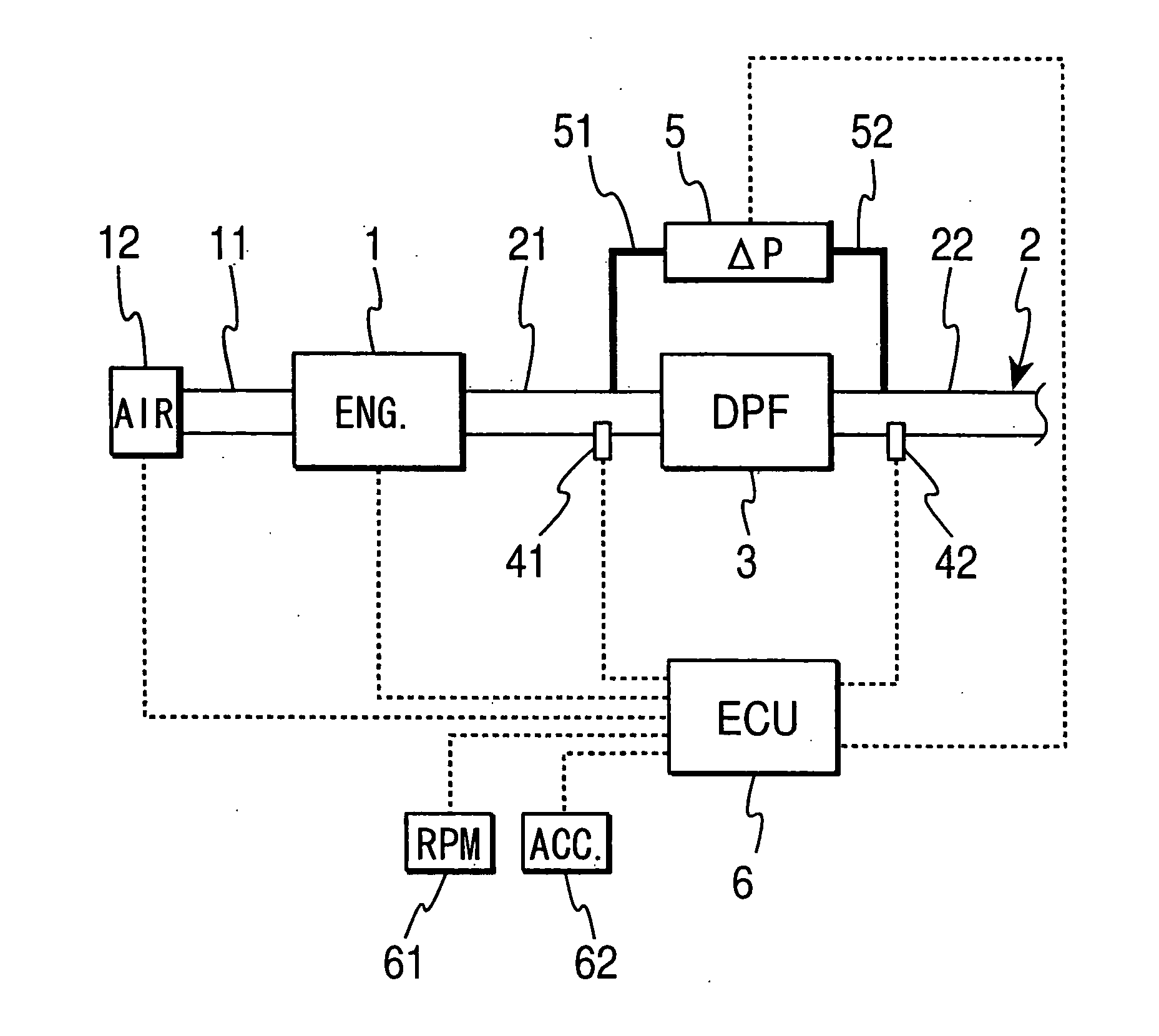
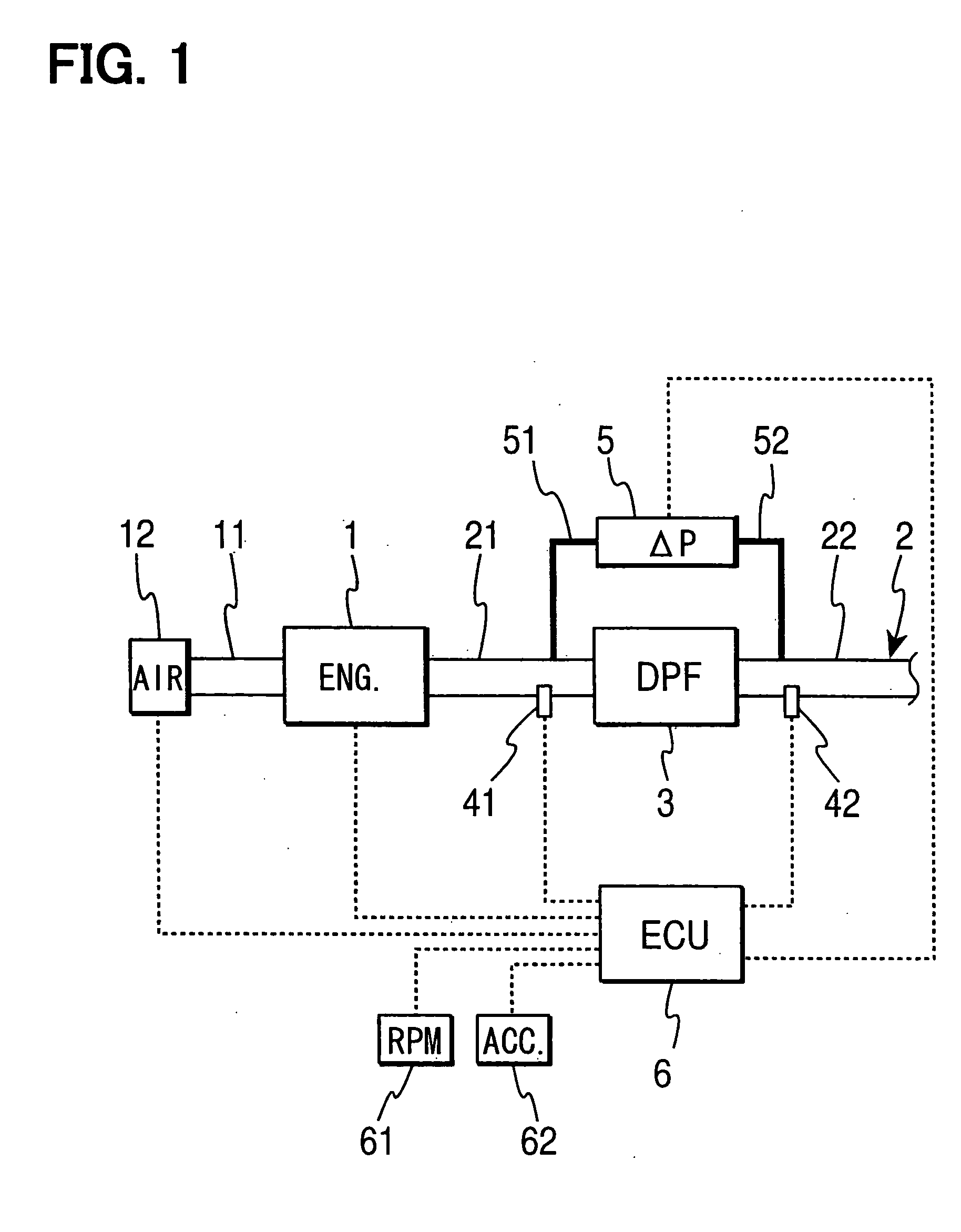
[0028] Referring to FIG. 1, an exhaust gas purification device for a diesel engine according to the example embodiment of the present invention is illustrated. The diesel engine 1 is connected with an intake passage 11 for supplying intake air into an engine combustion chamber and with an exhaust passage 2, through which exhaust gas discharged from the engine combustion chamber flows. An air flow meter 12 is located in the intake passage 11 to measure an amount of the intake air flowing through the intake passage 11. A diesel particulate filter (DPF) 3 is located in the exhaust passage 2.

[0029] The DPF 3 has a filter main body, which is formed of a porous ceramic such as cordierite or silicon carbide molded in a honeycomb shape. Each one of flow paths of the filter main body is blocked on an inlet side or an outlet side. The exhaust gas discharged from the engine 1 into an exhau...


PUM


Abstract

A diesel particulate filter (DPF) for trapping exhaust particulates is located in an exhaust passage of a diesel engine. Deposit amounts of a soluble organic fraction (SOF) as an organic solvent soluble component and soot as a solid carbon component of exhaust particulate components deposited in the DPF are estimated respectively. When the SOF deposit amount reaches an SOF elimination execution deposit amount, the DPF is heated to or over relatively low SOF combustion temperature to execute SOF elimination treatment. When the soot deposit amount reaches a soot elimination execution deposit amount, the DPF is heated to or over relatively high soot combustion temperature to execute soot elimination treatment. The SOF elimination treatment is executed before the SOF becomes excessive to prevent rapid combustion of the soot due to combustion of the SOF.

Description

CROSS REFERENCE TO RELATED APPLICATION [0001] This application is based on and incorporates herein by reference Japanese Patent Application No. 2005-111704 filed on Apr. 8, 2005. BACKGROUND OF THE INVENTION [0002] 1. Field of the Invention [0003] The present invention relates to an exhaust gas purification device for an internal combustion engine having a particulate filter for trapping exhaust particulates discharged from the engine. In particular, the present invention relates to deposit amount calculation of each component of exhaust particulates and regeneration treatment of a particulate filter of an exhaust gas purification device for an internal combustion engine. [0004] 2. Description of Related Art [0005] For environmental protection, an exhaust gas purification device is introduced to reduce air pollutants discharged from an exhaust port of an internal combustion engine. As a conventional exhaust gas purification device, a catalyst system such as an oxidation catalyst, a N...

Claims


Application Information

Patent Timeline
IPC IPC(8): F01N3/00
CPCF01N3/023F01N9/002F01N11/002Y10S55/30F02D41/029F02D2200/0812Y02T10/47F02D41/024Y02T10/40
Inventor KUBOSHIMA, TSUKASAYAHATA, SHIGETOTOCHIKAWA, KAZUHARU
Owner DENSO CORP
Why Eureka
Try Eureka