Method to control auto-ignition in an internal combustion engine equipped with variable valve timing control

a technology of variable valve timing and control method, which is applied in the direction of electric control, machines/engines, instruments, etc., can solve the problems of unplanned and uncoordinated, rapid and uneven combustion of air/fuel charge in the cylinder, and auto-ignition of air/fuel combustion charge generally occurring under severe engine operation

Inactive Publication Date: 2006-10-12
DELPHI TECH INC
View PDF5 Cites 9 Cited by
  • Summary
  • Abstract
  • Description
  • Claims
  • Application Information

AI Technical Summary

Benefits of technology

[0013] Another aspect of the invention includes implementing the individual cylinder knock control strategy, comprising determining which cylinder is being monitored, determining a scheduled cam position, selecting a knock signal threshold based upon the monitored cam position and the scheduled

Problems solved by technology

The auto-ignition of an air/fuel combustion charge generally occurs under severe engine operation, including high load operation or high temperature operation, especially in engines operating at high compression ratios.
Under such conditions, a combination of thermal energy transferred to the combustion charge, coupled with increase in combustion pressure due to engine load, causes uncontrolled, rapid, and uneven combustion of the air/fuel charge in the cylinder.
A auto-ignition event creates unplanned and uncoordinated pressure pulses in the combustion chamber that induce thermal and vibrational stresses on various engine components, including pistons, crankshaft, and intake and exhaust valves.
The induced thermal and vibrational stresses may lead to catastrophic failures of the engine components.
Detection of spark knock in an internal combustion engine is confounded by the presence of signal noise and vibrations incidental to normal combustion and engine operation.
Mechanical noise, as may be caused by cl

Method used


Image

  • Method to control auto-ignition in an internal combustion engine equipped with variable valve timing control
  • Method to control auto-ignition in an internal combustion engine equipped with variable valve timing control
  • Method to control auto-ignition in an internal combustion engine equipped with variable valve timing control

Examples


Embodiment Construction

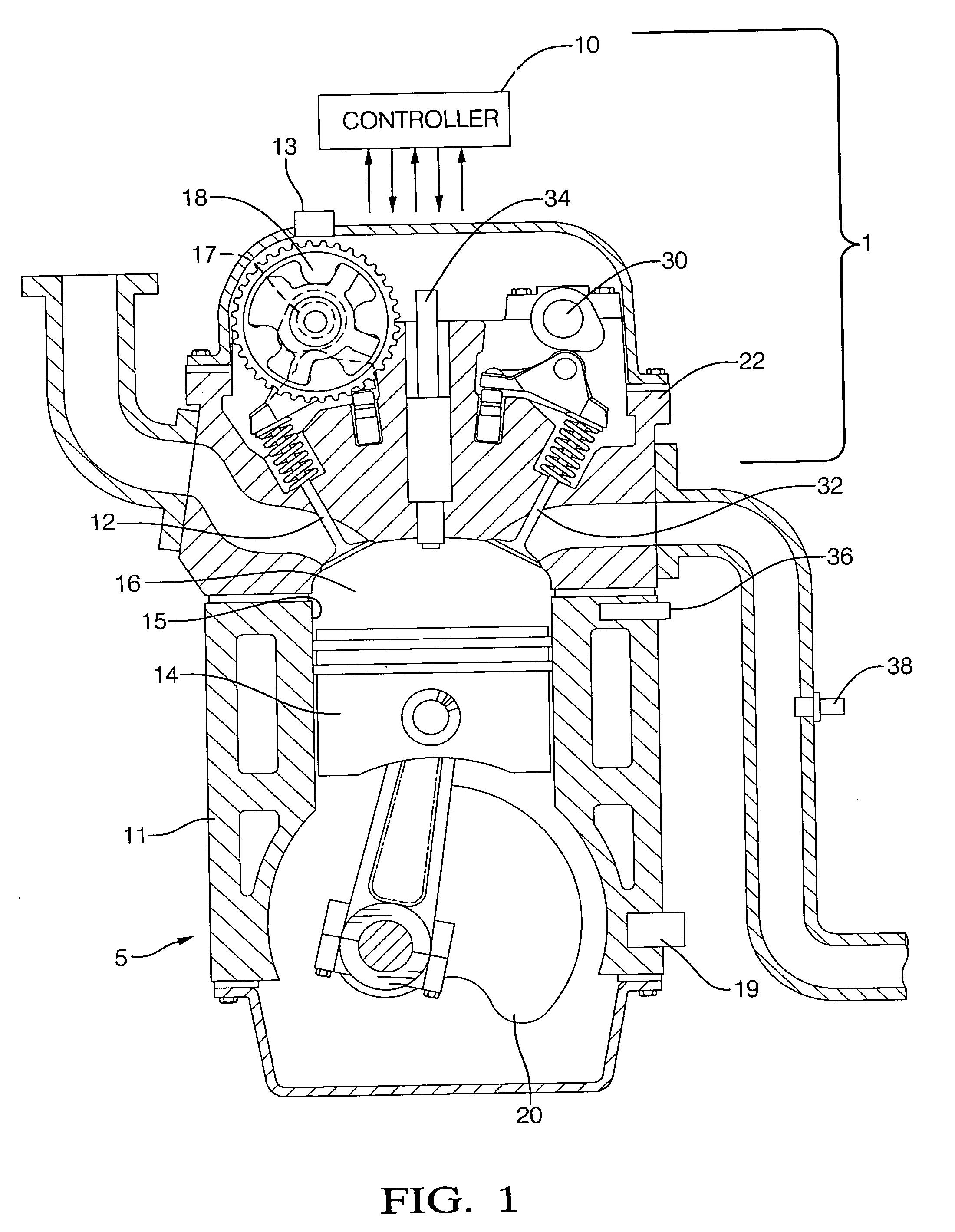
[0019] Referring now to the drawings, wherein the showings are for the purpose of illustrating the invention only and not for the purpose of limiting the same, FIG. 1 shows an internal combustion engine and control system 1 which has been constructed in accordance with an embodiment of the present invention. The exemplary internal combustion engine and control system 1 comprises a spark-ignition port fuel injection engine 5 and a controller 10. The exemplary engine 5 is equipped with a dual overhead cam system including a variable cam phasing system 18 attached to the intake camshaft 17, and operable to control opening and closing times of intake valves 12. The engine 5 includes base engine components, sensing devices, output systems and devices, described in detail hereinafter. The exemplary controller 10 comprises an electronic controller signally connected to a plurality of engine and vehicle sensors, operably connected to a plurality of output devices, and containing various pre...


PUM


Abstract

A method and control system to accomplish knock control on a multi-cylinder spark-ignition internal combustion engine equipped variable cam phasing system, comprising monitoring cam position, crankshaft position, and, engine knock signal, determining cam position relative to crankshaft position, and implementing either a global cylinder knock control strategy or an individual cylinder knock control strategy, based upon whether the determined cam position relative to crankshaft position is near a default position, the determined cam position indicates the variable cam phasing system is operating in a transient mode, or, the determined cam position relative to crankshaft position is substantially different from the default position.

Description

TECHNICAL FIELD [0001] This invention pertains generally to internal combustion engine control systems, and more specifically to spark-ignition control of an internal combustion engine equipped with a variable valve timing system. BACKGROUND [0002] Modern spark-ignition internal combustion engines are generally equipped with sensors and associated control systems operable to detect auto-ignition of a combustion charge, also referred to as detonation or engine knock. The auto-ignition of an air / fuel combustion charge generally occurs under severe engine operation, including high load operation or high temperature operation, especially in engines operating at high compression ratios. Under such conditions, a combination of thermal energy transferred to the combustion charge, coupled with increase in combustion pressure due to engine load, causes uncontrolled, rapid, and uneven combustion of the air / fuel charge in the cylinder. As such, knock occurs when portions of the air / fuel combus...

Claims


Application Information

Patent Timeline
IPC IPC(8): F02P5/152
CPCF01L1/3442F01L2800/00F01L2810/04F02D13/0238Y02T10/18F02P5/1522G01L23/225Y02T10/46F02D2041/001Y02T10/12Y02T10/40
Inventor RAMAPPAN, VIJAYLOVEGROVE, BRIAN R.KARAU, PHILIP ALLENGARCIA, SERGIO EDUARDO
Owner DELPHI TECH INC
Why Eureka
Try Eureka