Display apparatus and inspection method

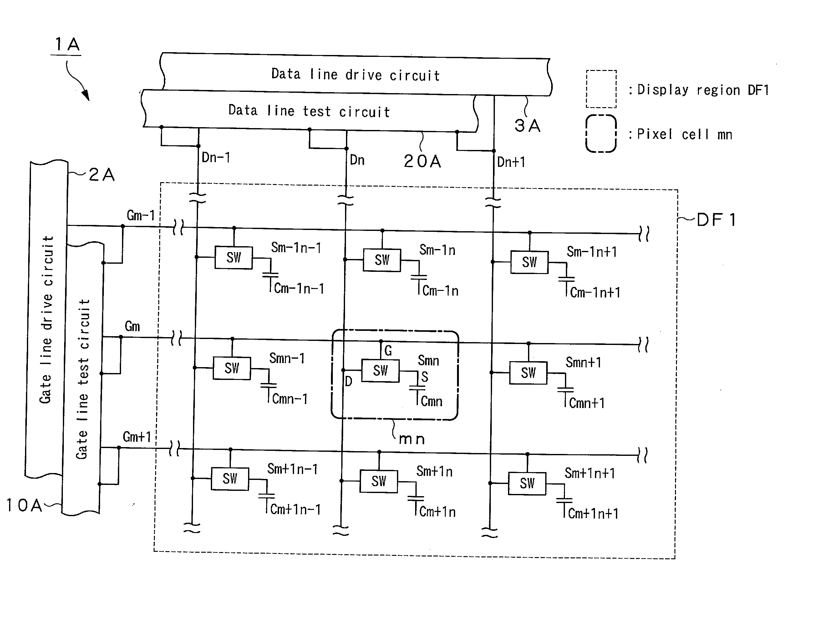
a technology of liquid crystal display apparatus and inspection method, which is applied in the direction of identification means, instruments, static indicating devices, etc., can solve the problems of uneven display pattern in the display region, adverse effects on image quality of images displayed on liquid crystal display apparatus having such a configuration, etc., to reduce test time, prevent defective components, and facilitate data line testing

Active Publication Date: 2006-10-12
SONY CORP
View PDF6 Cites 18 Cited by
  • Summary
  • Abstract
  • Description
  • Claims
  • Application Information

AI Technical Summary

Benefits of technology

[0013] In view of the above identified problem, it is desirable to provide a display apparatus comprising pixel cells arranged to form a matrix and an inspection method that can detect short-circuiting in the gate lines and the data lines for driving the pixel cells and also short-circuiting relating to the pixel cells easily in a short period of time even when the display region of the display apparatus is divided.
[0019] With this arrangement, it is possible to determine if a data line is short-circuited or not according to the digital value output from the corresponding first detector logic circuit and also if a gate line is short-circuited or not according to the digital value output from the corresponding second detector logic circuit. Thus, the detection error, if any, is less influential if compared with an arrangement that deals with analog values so that it is easy to test the data lines and it is possible to reduce the test time.
[0020] Additionally, if the display apparatus is a liquid crystal display apparatus, it is possible to detect any short-circuiting in the stage of containing liquid crystal in a hermetically sealed condition so that it is possible to prevent defective components from being mounted and hence reduce the unnecessary cost that arises due as a result of mounting such defective components. Additionally, it is also possible to detect any short-circuiting after the stage of containing liquid crystal in a hermetically sealed condition. In other words, it is possible to detect any short-circuiting throughout the manufacturing process and the result of the short-circuiting detecting operation can be fed back to the manufacturing process to further improve the manufacturing efficiency.
[0022] A display apparatus according to the invention comprises first comparator circuits, each of which is adapted to compare the electric potential of the corresponding data line input to it and a reference potential, which is the expected value of the input potential of the data line, and binarize the outcome of the comparison so as to output the binarized outcome and second comparator circuits, each of which is adapted to compare the electric potential of the corresponding gate line input to it and a reference potential, which is the expected value of the input potential of the gate line, and binarize the outcome of the comparison so as to output the binarized outcome. With this arrangement, it is possible to detect any short-circuiting highly accurately by selecting an appropriate reference voltage depending on the short-circuit resistance value to be detected.

Problems solved by technology

However, with the above described configuration, it is necessary to arrange elements other than the pixel cells in the display region of the liquid crystal display apparatus to consequently make the layout pattern in the display region uneven.
Then, there arises a problem that the image quality of the image displayed on a liquid crystal display apparatus having such a configuration is adversely affected by the configuration.

Method used


Image

  • Display apparatus and inspection method
  • Display apparatus and inspection method
  • Display apparatus and inspection method

Examples


first embodiment

[0043] Referring to FIG. 4 that illustrates the first embodiment of data line test circuit 20A, it comprises transistors Tr1n (n: natural number) connected to the respective data lines Dn and detector logic circuits 21 When short-circuit arises in the data lines Dn, the short-circuiting site shows a resistance value (short-circuit resistance) Rs.

[0044] When detecting short-circuiting in the data lines Dn, the transistors Tr1n are energized (ON) and a predetermined power supply potential VDD or the ground potential VSS is connected to the data lines Dn by way of the transistors Tr1n. The size of the transistors Tr1n is so adjusted as to show a high ON resistance Rt, which is the current to voltage ratio in the energized state.

[0045]FIG. 5 is a circuit diagram of an equivalent circuit of the data line test circuit that can be used when a transistor Tr1n is turned on in order to detect short-circuiting in the data lines Dn. Referring to FIG. 5, each of the data lines is connected at ...

second embodiment

[0058] Now, the second embodiment of data line test circuit 20A′ will be described by referring to FIG. 7. As seen from FIG. 7, the data line test circuit 20A′ differs from the data line test circuit 20A of the first embodiment in that the detector logic circuits 21 are replaced by comparator circuits 25 and buffers 26.

[0059] Each of the comparator circuits 25 receives the data line potential Vd of the corresponding data line Dn at one of its input terminals and a reference voltage Vref at the other input terminal as input. The comparator circuit 25 compares the data lint potential Vd and the reference voltage Vref and binarizes the outcome of the comparison. The binary signal representing the outcome of the comparison is output by way of the corresponding buffer 26. The comparator circuit 25 may be a differential input circuit or a comparator. Thus, it is easy to test the data lines and it is possible to reduce the test time because the comparator circuit 25 outputs the detected s...


PUM

PropertyMeasurementUnit
capacitanceaaaaaaaaaa
resistanceaaaaaaaaaa
electric potentialaaaaaaaaaa

Abstract

The test circuit of a display apparatus according to the invention detect short-circuiting in each of the data lines Dn by inputting the electric potential Vd of the data line Dn connected to the corresponding one of high resistance first short-circuiting detecting resistors Tr1n connecting a predetermined electric potential and the data line Dn to the corresponding one of first detector logic circuits and binarizing and outputting the input electric potential Vd of the data line Dn by referring to a predetermined threshold value and also detect short-circuiting in each of the gate lines Gm by inputting the electric potential of the gate line Gm connected to the corresponding one of high resistance second short-circuiting detecting resistors connecting a predetermined electric potential and the gate line Gm to the corresponding one of second detector logic circuits and binarizing and outputting the input electric potential of the gate line by referring to a predetermined threshold value. The defects (short-circuits) produced in the process of manufacturing the display apparatus can be inspected by a simple technique.

Description

RELATED APPLICATION DATA [0001] This application is divisional of U.S. patent application Ser. No. 11 / 136,960, filed May 25, 2005, which is incorporated herein by reference to the extent permitted by law. This application claims the benefit of priority to Japanese Patent Application No. JP 2004-162048 filed in the Japanese Patent Office on May 31, 2004, which also is incorporated herein by reference to the extent permitted by law.BACKGROUND OF THE INVENTION [0002] 1. Field of the Invention [0003] This invention relates to a display apparatus comprising pixel cells arranged to form a matrix. More particularly, the present invention relates to an inspection method for detecting defects in the gate lines and the data lines for driving pixel cells of a display apparatus and also to a display apparatus adapted to such an inspection method. [0004] 2. Description of the Related Art [0005] Liquid crystal display apparatus employing an active matrix system have been and being popularly used ...

Claims


Application Information

Patent Timeline
Patent Type & Authority Applications(United States)
IPC IPC(8): G01R31/00G01R31/02G02F1/13G02F1/133G09F9/00G09G3/00G09G3/20G09G3/36
CPCG09G3/006Y10S345/904G09G3/3666
Inventor ANDO, NAOKI
Owner SONY CORP
Why Eureka
Try Eureka