Relay apparatus and electric appliance

a technology of relays and electric appliances, applied in the direction of frequency-division multiplexes, coupling device connections, instruments, etc., can solve the problems of large installation work scale, inducing impedance fluctuations, and complicated indoor power line wiring

Active Publication Date: 2006-10-12
PANASONIC CORP
View PDF12 Cites 47 Cited by
  • Summary
  • Abstract
  • Description
  • Claims
  • Application Information

AI Technical Summary

Benefits of technology

[0017] In the above-described configuration, when performing wire communications indoors and the like, communications using a suitable wire ...

Problems solved by technology

This requires a large scale of installation work before the communication system goes into operation.
However, indoor power line wiring is very complicated and each building has significantly different conditions.
Moreover, since wide-ranging types of electric appliances are connected to such power lines, various noises can occur and induce impedance fluctuations.
Therefore, compared to when performing communications via an exclusive wire transmission line, when performing communications via a power line, there is a higher possibility that communication speed slows down considerably or communication quality deteriorates due to decrease in a S/N ratio (signal-to-noise ratio).
In other words, while power line communications are very convenient in that their transmission lines can be easily secured, there are cases in which sufficient communication speed or desirable communication quality cannot be achieved in an environment where various users perform power line communications.
However, when newly preparing an exclusive wire transmission line, users face situations where wire installation work becomes necessary or where newly installed wires are left exposed in the room.
This ruins the benefit of convenience afforded by power line communications.
However, when connecting different electric appliances to the same wiring, an impedance mismatching inevitably occurs and causes problems, since such connection configuration is not standardized.
For instance, when connecting a PLC modem to a coaxial line that connects a TV antenna and a TV receiver, the impedance of the modem causes an impedance mismatching on a line...

Method used


Image

  • Relay apparatus and electric appliance
  • Relay apparatus and electric appliance
  • Relay apparatus and electric appliance

Examples


first embodiment

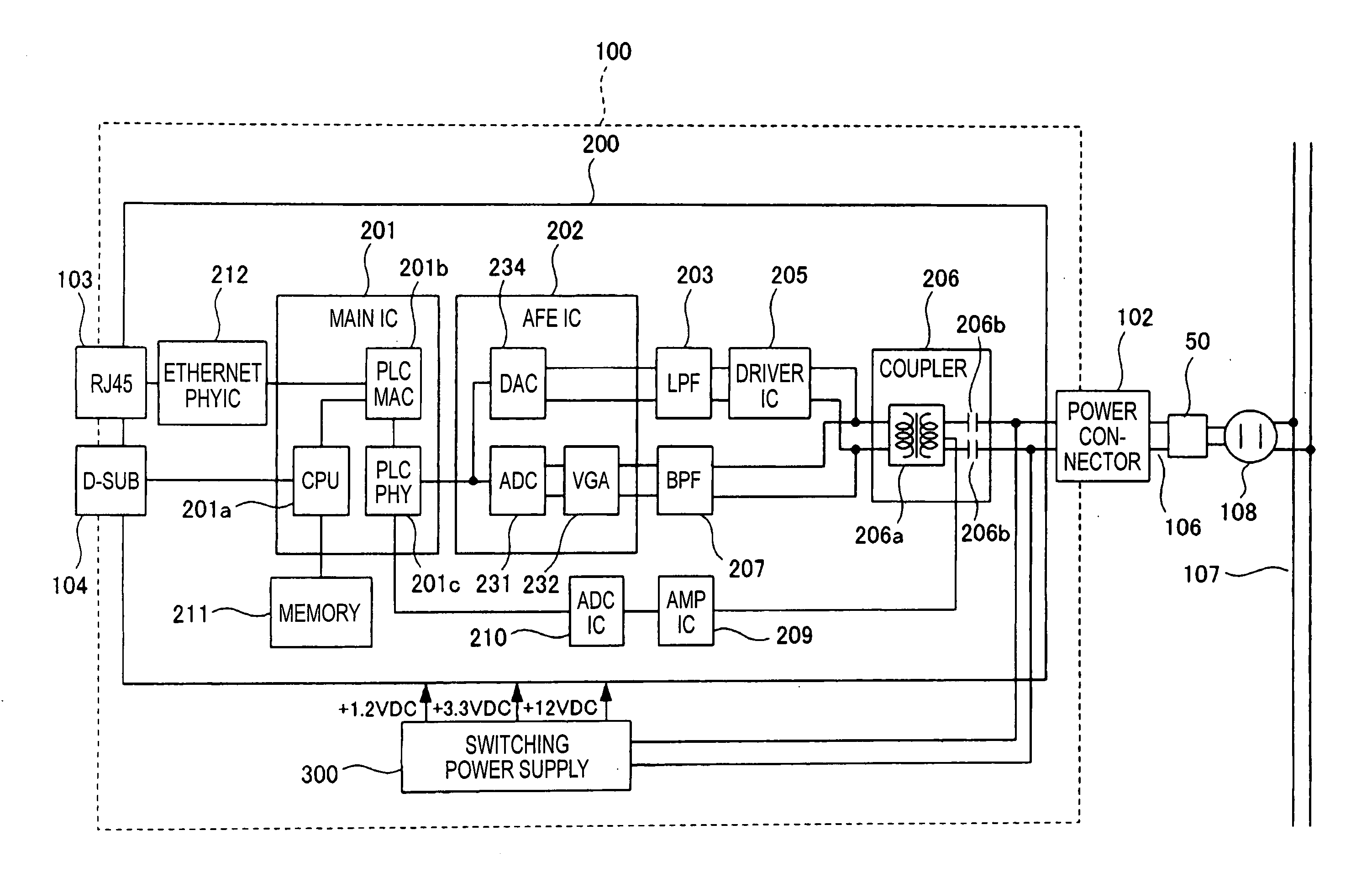
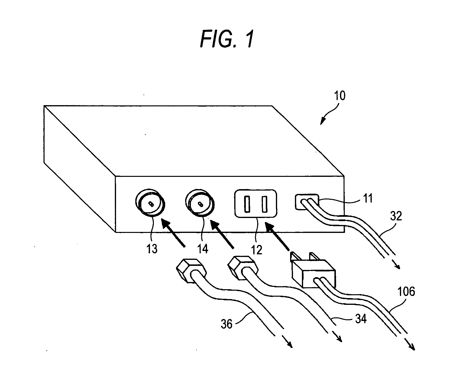
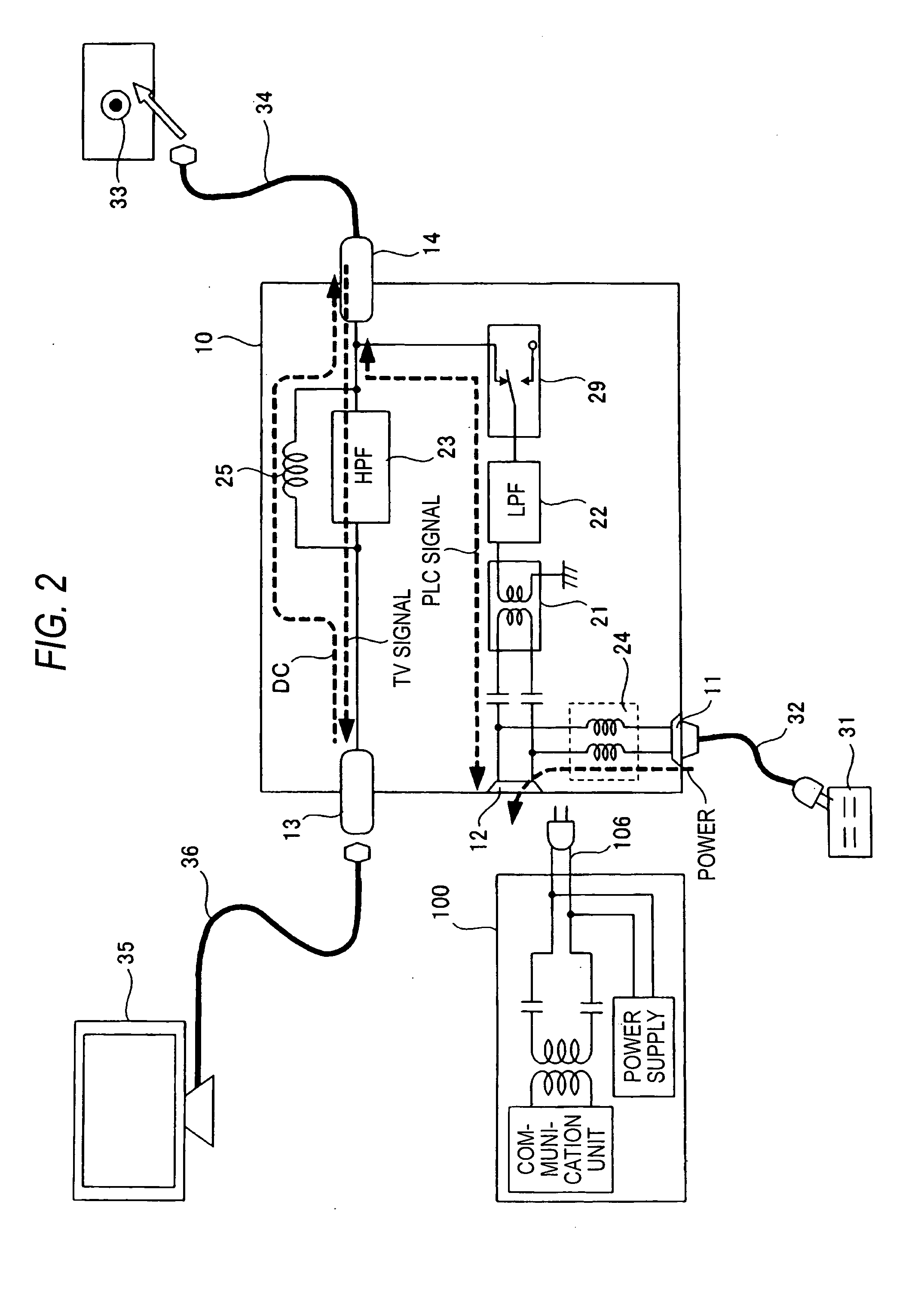
[0043] In the present embodiment, for example, a communication system performs communications between different communication apparatuses using, for example, a power line as a transmission line. In this case, as shown in FIGS. 1 and 2, relay apparatus 10 connects to power line communication apparatus 100 which functions as a PLC modem performing multicarrier communication (hereinafter referred to as “multicarrier communication apparatus”).

[0044] In the examples shown in FIGS. 1 and 2, relay apparatus 10 is used to allow a home-use line (a coaxial line) that connects a TV antenna and a TV receiver to serve as a transmission line for multicarrier communication apparatus 100.

[0045] Relay apparatus 10 of the present embodiment includes modem connecting terminal 12, power line connecting terminal 11, electric appliance connecting terminal 13 and coaxial connecting terminal 14. Modem connecting terminal 12 is an example of a second terminal to be connected to multicarrier communication ...

second embodiment

[0078] The second embodiment of a relay apparatus is described in the following with reference to FIGS. 9 and 10A through 10E. The second embodiment is a modified example of the first embodiment. Components corresponding to those of the first embodiment in FIG. 9 are assigned the same numbers. Components and operations different from those of the first embodiment are described in the following.

[0079] Relay apparatus 10A according to the second embodiment includes the above-described power line connecting terminal 11 for external connection, modem connecting terminal 12, electric appliance connecting terminal 13, coaxial connecting terminal 14 and line connecting terminal 18. Line connecting terminal 18 connects to a telephone line or the like. As with the first embodiment, relay apparatus 10A further includes couplers 21, communication filters 22 and 23, and power filters 24 and 25. Further, relay apparatus 10A includes selector 29, and switches 26a and 26b. Selector 29 selects and...

third embodiment

[0089] A relay apparatus according to the third embodiment is described in the following with reference to FIG. 11. The third embodiment is a modified example of the first embodiment. Components corresponding to those of the first embodiment in FIG. 11 are assigned the same numbers. Components and operations different from those of the first embodiment are described in the following.

[0090] Relay apparatus 10B according to the third embodiment, as with the first embodiment, includes coupler 21, communication filters 22 and 23, and power filters 24 and 25. Relay apparatus 10B further includes switches 26a and 26b that turn on / off connection to power filter 24, terminal resistors 27a and 27b that terminate a signal transmission line or a connecting terminal, switch 28 that turns on / off connection to terminal resistor 27a, and selector 29 that selects a transmission line for power line communications and turns on / off connection to terminal resistor 27b. The transmission line can be swi...


PUM


Abstract

A relay apparatus includes a plurality of connecting terminals, such as a modem connecting terminal, a power line connecting terminal, an electric appliance connecting terminal and an antenna line connecting terminal; a selector that selects at least one connecting terminal from among the plurality of connecting terminals to transmit and receive a communication signal; and a control circuit that controls the selector. The relay apparatus further includes a first communication filter that passes signals in a frequency band used for communication by a power line communication modem and that blocks signals in other frequency bands, and a second communication filter that passes signals in a frequency band used for communication by another electric appliance and that blocks signals in other frequency bands.

Description

BACKGROUND [0001] 1. Field of the Invention [0002] The present invention relates to a relay apparatus that is connected to a wire transmission line and a communication apparatus so as to relay communication signals, in a system that performs wire communications, including power line communications using, for example, a home-use power line as a transmission line. [0003] 2. Description of Related Art [0004] When using a terminal such as a computer for wire data communications at homes, offices, factories and the like, it is usually necessary to install wires such as cables and terminals to be used as transmission lines at such locations where they are needed. This requires a large scale of installation work before the communication system goes into operation. [0005] However, at homes, offices and factories, commercial power supply, for example, 100V AC-50 / 60 Hz in Japan, 120V AC-60 Hz in the United States of America is generally used. Therefore, power lines (electric lamp lines) for s...

Claims


Application Information

Patent Timeline
IPC IPC(8): H04L25/00
CPCH04B3/54H04B2203/5454H04B2203/5445
Inventor KOGA, HISAOIGATA, YUJIYUKIZANE, RYOTAICHIHARA, FUMIOOISHI, MUTSUHIKO
Owner PANASONIC CORP
Why Eureka
Try Eureka