Four point contact structural spacer grid

Inactive Publication Date: 2006-10-12
WESTINGHOUSE ELECTRIC CORP
View PDF20 Cites 22 Cited by
  • Summary
  • Abstract
  • Description
  • Claims
  • Application Information

AI Technical Summary

Benefits of technology

[0012] These needs, and others, are met by the present invention which provides for a four contact point strap that may be used on either a support grid or Intermediate Flow Mixing grid and which has an elongated fuel rod contact surface. The straps are structured to form generally square cells. Within each cell are two elongated springs and two elongated dimples. The elongated springs and elongated dimples are non-coplanar within a cell. Thus, in each cell the fuel rod is contacted at four points. Because there are only four protuberances extending into each cell, instead of six as in the prior art, the pressure drop is reduced. This also allows for a reduced height support grid which in turn further reduces the pressure drop as the coolant contacts the support grid for a shorter distance. Additionally, because there are only four contact points, the number of points where fretting wear occurs is reduced. Further, because the springs and dimples are elongated, the contact pressure applied to the fuel rod may be reduced, thus further reducing fretting while still contacting the fuel rod with generally the same force as in the prior art support grids. A grid assembled with such straps may be used in place of either a support grid or Intermediate Flow Mixing grid.

Problems solved by technology

A common problem in the PWR fuel industry is vibration of the fuel rod / support system as a natural response to coolant flow.
This phenomenon is manifested as grid-to-rod fretting, which can ultimately lead to a breach in the fuel rod cladding and leakage of nuclear fuel material into the coolant.
These protuberances create an undesirable pressure drop.

Method used


Image

  • Four point contact structural spacer grid
  • Four point contact structural spacer grid
  • Four point contact structural spacer grid

Examples


Embodiment Construction

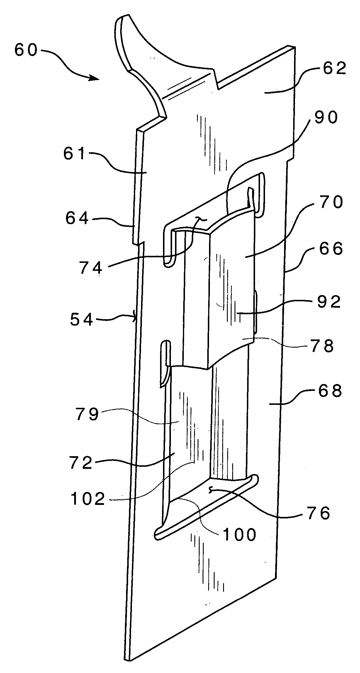
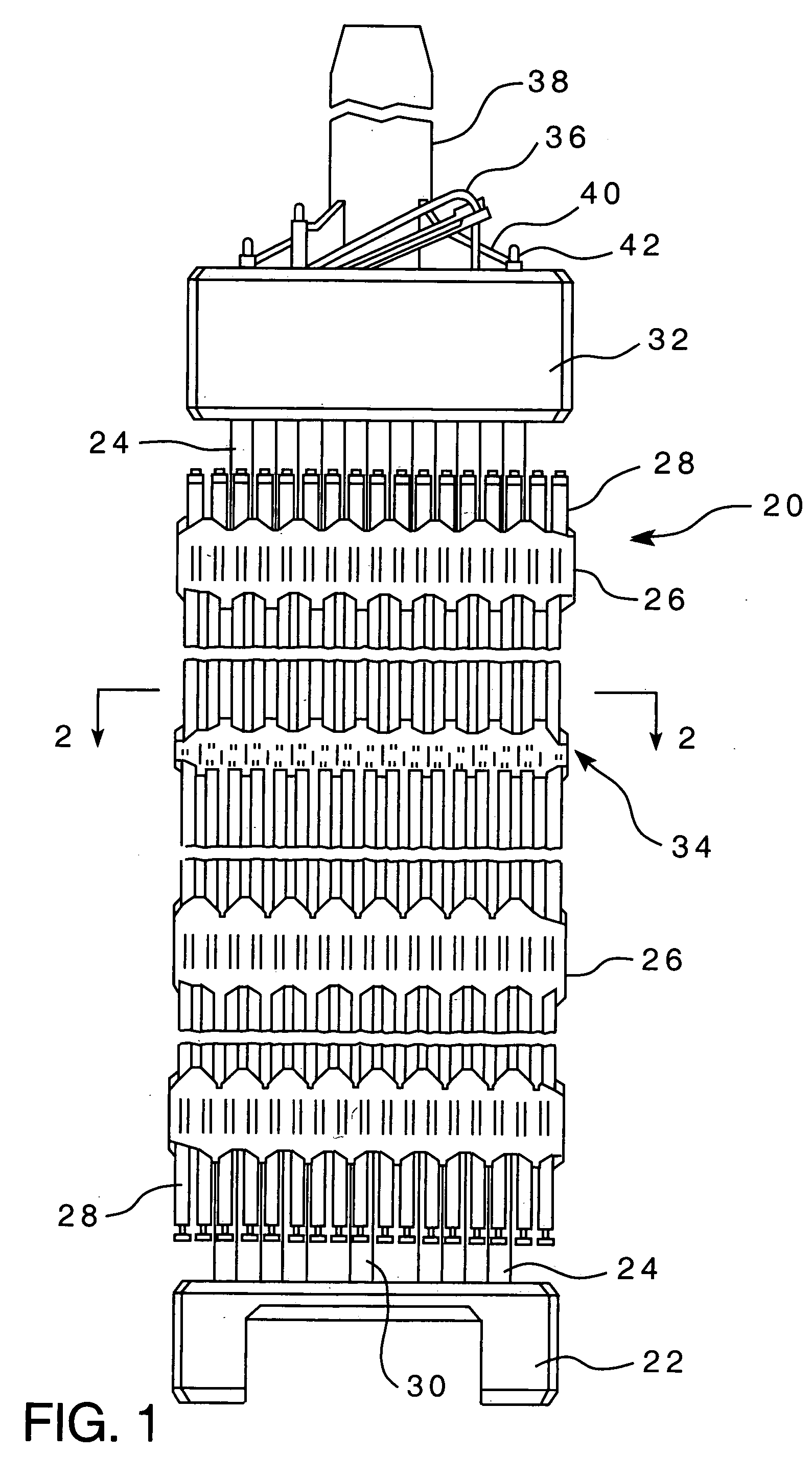
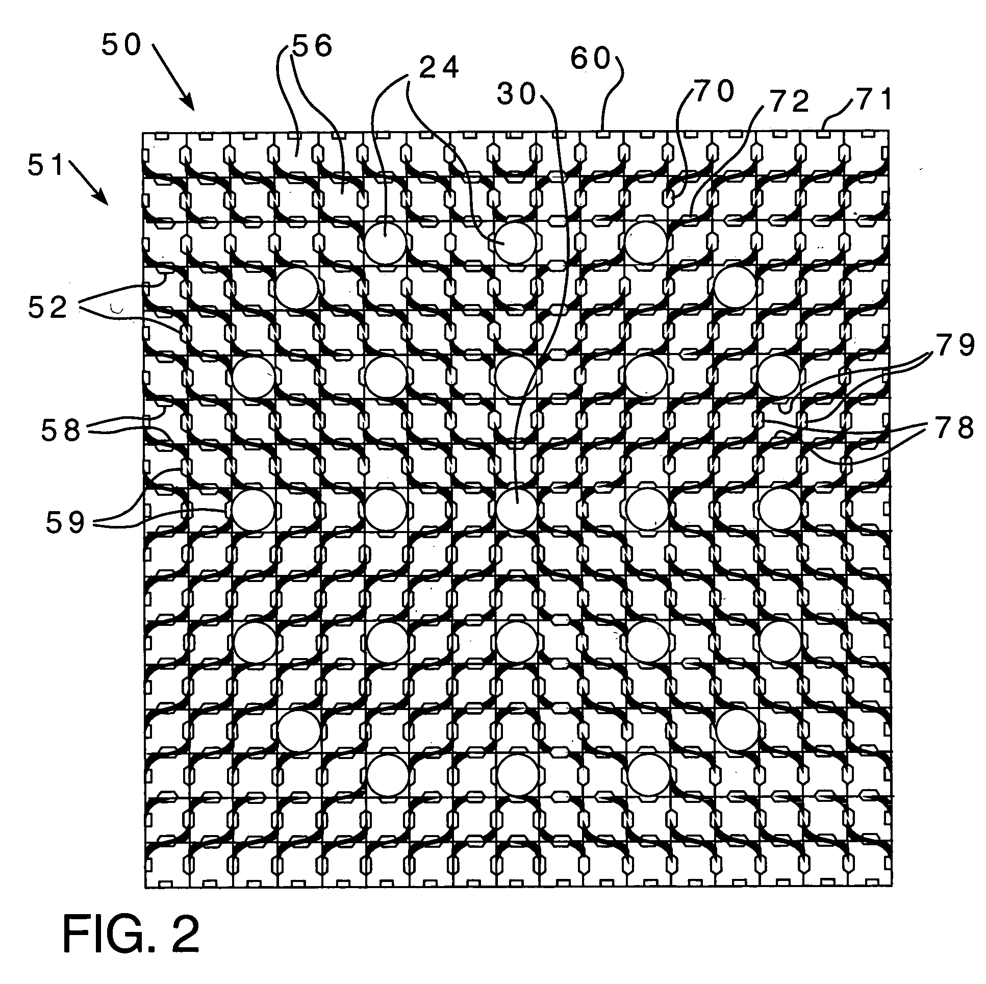
[0021] As shown in FIG. 1, a fuel assembly 20 for a nuclear reactor is disposed in a water vessel (not shown) having an inlet at the bottom and an outlet at the top. The fuel assembly 20 comprises a lower end structure or bottom nozzle 22 for supporting the fuel assembly 20 on the lower core plate (not shown) in the core region of a reactor (not shown); a number of longitudinally extending control rod guide tubes, or thimbles 24, projecting upwardly from the bottom nozzle 22; a plurality of transverse support grids 26 axially spaced along the guide thimbles 24; an organized array of elongated fuel rods 28 transversely spaced and supported by the grids 26; an instrumentation tube 30 located in the center of the assembly; and an upper end structure or top nozzle 32 attached to the upper ends of the guide thimbles 24, in a conventional manner, to form an integral assembly capable of being conventionally handled without damaging the assembly components. The bottom nozzle 22 and the top ...


PUM


Abstract

A four point contact grid for a nuclear fuel assembly, that is structured to engage at least one generally cylindrical fuel rod. The four point contact grid includes a plurality of elongated, generally flat straps including a first set of straps and a second set of straps, each strap having a plurality of cell portions. The straps are divided into a first set and a second set. The first set of straps are disposed in a spaced parallel relation to each other. The second set of straps are also disposed in a spaced parallel relation to each other and are generally perpendicular to the first set of straps. The first set of straps and second set of straps are coupled to each other thereby forming a plurality of generally square cells. Each strap cell portion has at least one protrusion. Each the strap cell portion further has only a single protrusion extending into each cell. Each the protrusion is either an elongated spring or an elongated dimple. Thus, each the fuel rod is contacted by only four protrusions in each cell.

Description

BACKGROUND OF THE INVENTION [0001] 1. Field of the Invention [0002] The present invention relates to nuclear reactor fuel assemblies and more particularly to an array for supporting fuel rods wherein the array consists of a plurality of straps disposed in a grid-like pattern of cells wherein each cell has four contact points structured to engage a fuel rod. [0003] 2. Description of the Prior Art [0004] In a typical pressurized water reactor (PWR), the reactor core is comprised of a large number of generally vertically, elongated fuel assemblies. The fuel assemblies include a frame assembly structured to support a plurality of fuel rods. The fuel assembly includes a top nozzle, a bottom nozzle, a plurality of spacer grids, intermediate flow mixing grids, and a plurality of thimble tubes. The grids are attached to the plurality of elongated thimble tubes which extend vertically between the top and bottom nozzles. The thimble tubes typically receive control rods, plugging devices, or i...

Claims


Application Information

Patent Timeline
IPC IPC(8): G21C3/34
CPCG21C3/322G21C3/352G21C3/356Y02E30/38G21Y2002/302G21Y2002/304G21Y2004/30G21Y2002/201Y02E30/30G21C3/24
Inventor MARZEAN, MICHAEL A.
Owner WESTINGHOUSE ELECTRIC CORP
Why Eureka
Try Eureka