
Optical transmission device and optical transmission system

Inactive Publication Date: 2006-10-12
PANASONIC CORP
View PDF4 Cites 9 Cited by
  • Summary
  • Abstract
  • Description
  • Claims
  • Application Information

AI Technical Summary

Benefits of technology

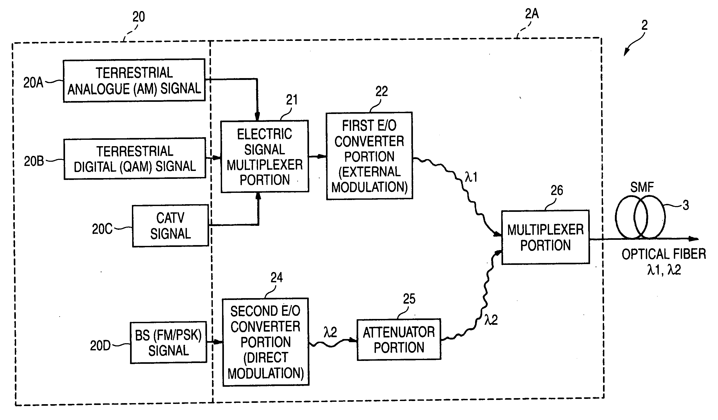
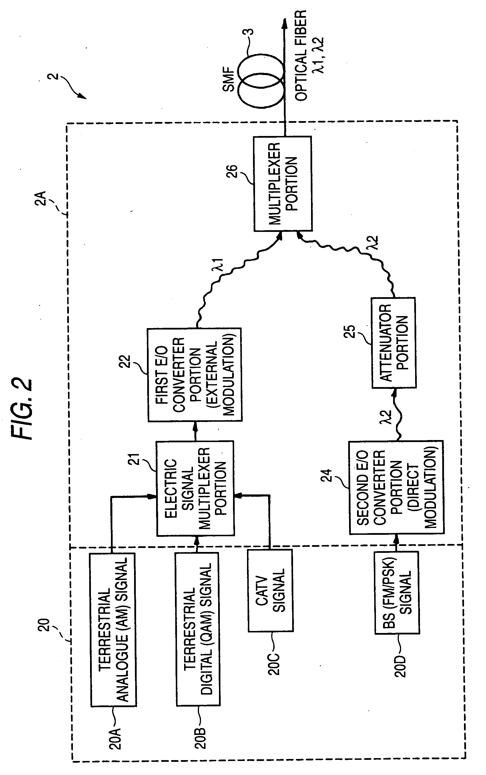
[0018] The external modulation process is applied to the first optical signal, which is modulated by the transmission signal on the low frequency side for which the low noise characteristic and distortion characteristic are required, out of the wideband frequency multiplexing electric signals. Since the wavelength “chirping” (extension of the wavelength) is small when the optical modulation is executed by this external modulation process, degradation of various transmission characteristics due to the wavelength scattering, for example, the distortion degradation due to the scattering of the optical signal spectrum, or the like can be avoided.
[0019] In contrast, the direct modulation process is applied to the second optical signal, which is modulated by the transmission signal on the high frequency side whose request for the transmission characteristic is not so high, to execute the E / O conversion. Normally the direct modulation type E / O converter is inexpensive in contrast to the external modulation type E / O converter, and a reduction in cost can be achieved.
[0023] According to this configuration, the optical level that is higher than the second optical signal, the request of the noise characteristic of which is not so high, by a predetermined value or more can be maintained with respect to the first optical signal whose request of the noise characteristic is high. Therefore, the predetermined CNR and in turn the good receiving characteristic can be maintained during the receiving operation.
[0026] Therefore, in the present invention, the level difference between two wavelengths is set higher by a level to estimate this peculiar phenomenon. Accordingly, since the optical signals having two wavelengths can be into the optical receiving unit to have the predetermined level difference, a predetermined CNR (Carrier to Noise Ratio) can be obtained even when the high power optical amplifier is used in the transmitting unit, and thus the good receiving characteristic can be maintained.
[0035] According to this configuration, the subscriber's home can receive the multi-channel video signal by a single O / E converting unit. Therefore, such signal can be received by the low-cost existing equipment correspondingly, and the optical transmission system capable of transmitting / receiving the multi-channel video signal over the wideband can be implemented at a low cost.

Problems solved by technology

However, according to the optical transmission system aiming at the above distortion improvement, since the E / O conversion is executed uniformly by the direct modulation process irrespective of the modulation system of the electric signal, a cost performance in the distortion improvement was not good in using a plurality of semiconductor lasers.
For this reason, the SBS suppress signal is often multiplexed and thus the frequency band is limited.
Under such circumstances, the wideband frequency-multiplexed video signal is difficult to transmit.

Method used


Image

  • Optical transmission device and optical transmission system
  • Optical transmission device and optical transmission system
  • Optical transmission device and optical transmission system

Examples


first embodiment

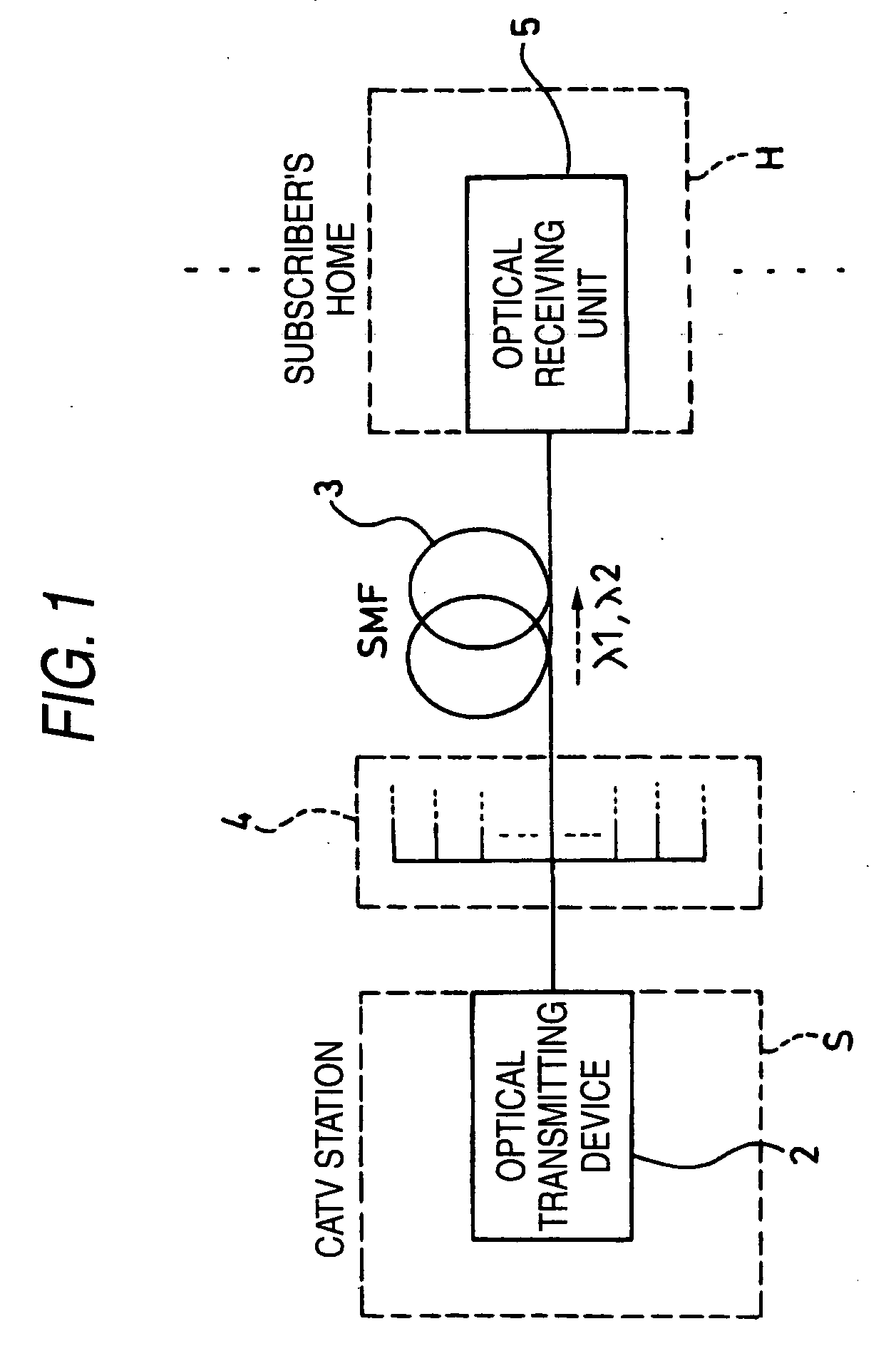
[0047]FIG. 1 shows an optical transmission system according to a first embodiment of the present invention. This optical transmission system constitutes a optical CATV network system, and includes an optical transmitting device 2, an optical transmitting unit 3, a branching unit 4, and an optical receiving unit 5.

[0048] Normally, when the transmission signal is optically modulated by the optical transmitting device, the external modulation process by which no scattering is generated in theory and which is excellent in the noise and the distortion characteristic is preferable. However, the external modulation process is readily affected by the nonlinear effect such as SBS, or the like, and the limitation is imposed on the frequency band by the signal superposed to suppress such effect.

[0049] For this reason, in the present invention in which the transmission signal whose frequency band is broadened particularly, etc. are used, the transmission signal on the high frequency side (the...

second embodiment

[0091] Next, an optical transmission system according to a second embodiment of the present invention will be explained with reference to FIG. 7 to FIG. 9 hereunder. Here, in the present embodiment, the same reference symbols are affixed to the same portions as those in the first embodiment to avoid their duplicated explanations.

[0092] A difference of an optical transmission system according to a second embodiment from the first embodiment is that, as shown in FIG. 7, the optical amplifier 6 is provide in a multi-stage fashion (in the present embodiment, optical amplifiers 6A, 6B in two stages) to distribute (or transmit over a long distance) the multi-channel signal (frequency multiplexing video signal) in response to a large number of subscribers. Accordingly, the present embodiment is constructed such that outputs of the first and second optical signals λ1, λ2 are increased.

[0093] The optical amplifier 6 amplifies optically the first and second optical signals λ1, λ2 of two wav...


PUM


Abstract

The subject of the present invention is to provide an optical transmitting device and an optical transmission system, capable of realizing an increase of multiple channels and an extension of a transmission distance at a low cost. In the present invention, the external modulation process is applied to a first optical signal (λ1), which is modulated by a transmission signal on a low frequency side for which low noise and distortion characteristics are required, out of the wideband frequency multiplexing electric signals by a first E / O converting unit (22). In contrast, the direct modulation process is applied to a second optical signal (λ2), which is modulated by a transmission signal on a high frequency side whose request for the transmission characteristic is not so high, by a second E / O converting unit (24) to execute an E / O conversion. As a result, an optical transmitting device and an optical transmission system, capable of realizing an increase of frequency range and multiple channels and an extension of a transmission distance can be manufactured at a low cost.

Description

TECHNICAL FIELD [0001] The present invention relates to an optical transmitting device and an optical transmission system, which can be used in the optical communication, the optical CATV, and the like. BACKGROUND ART [0002] In recent years, the CATV using the metal cable (e.g., coaxial cable) is spread. The multi-channel video signals in which various modulation-system signals are multiplexed are often transmitted from the CATV transmitting station as the transmission signal. [0003] Meanwhile, various optical transmission systems utilizing the optical fiber are developed. For example, in the optical CATV, or the like, a broader band of a transmission frequency is demanded to implement an increase of multiple channels. Also, in such broader band situation, the sub-carrier multiplexing transmission system (referred to as the “SCM optical transmission system” hereinafter) is effective in putting the low loss characteristic and the wide band characteristic of the optical fiber to pract...

Claims


Application Information

Patent Timeline
IPC IPC(8): H04B10/04H04B10/50H04J14/02
CPCH04B10/504H04B10/505H04J14/0234H04J14/0282H04J14/0226
Inventor TAKEUCHI, SACHIKOKIRII, SUSUMUNOJIMA, KAZUHIRO
Owner PANASONIC CORP
Learn More