Vacuum pump

a vacuum pump and vacuum technology, applied in the direction of liquid fuel engines, rotary/oscillating piston pump components, machines/engines, etc., can solve the problems of expensive grinding and lapping operations, and achieve the effect of resisting undesirable shifting of internal parts

Inactive Publication Date: 2006-10-12
RITCHIE ENG
View PDF99 Cites 19 Cited by
  • Summary
  • Abstract
  • Description
  • Claims
  • Application Information

AI Technical Summary

Benefits of technology

[0009] An advantage of the present invention is to provide a vacuum pump wherein the correct clearances between internal parts may be achieved as a function of machining processes during the manufacturing of the pump using standard machining centers such as lathes and mills. Therefore, grinding and lapping operations generally performed by a skilled technician are not required.
[0010] Another advantage of the present invention is to provide a vacuum pump design which inherently resists the undesirable shifting of internal parts.
[0011] Another advantage of the present invention is to provide a vacuum pump having a stator that may be manufactured from an inexpensive tube of material. In some embodiments the stator may be cylindrical.
[0012] Another advantage of several embodiments of the present invention are to provide a vacuum pump having a tubular stator and a novel chamber dividing plate. Some embodiments may further include an integrated cap having an exhaust valve.
[0013] Another advantage of several embodiments of the present invention is to provide a vacuum pump wherein the clearance between the stator and the rotors may be fixed by providing end plates having a shaft journal aperture precisely located relative to a flange that may be used to locate the stator.
[0014] Another advantage of several embodiments of the present invention is to provide a divider plate located within an internal cavity of the stator.

Problems solved by technology

This often includes expensive grinding and lapping operations.

Method used


Image

  • Vacuum pump
  • Vacuum pump
  • Vacuum pump

Examples


Embodiment Construction

[0038] While this invention may be embodied in many different forms, there are described in detail herein specific preferred embodiments. This description is an exemplification of the principles of the invention and is not intended to limit the invention to the particular embodiments described.

[0039] For the purposes of this disclosure, like reference numerals in the Figures shall refer to like features unless otherwise indicated.

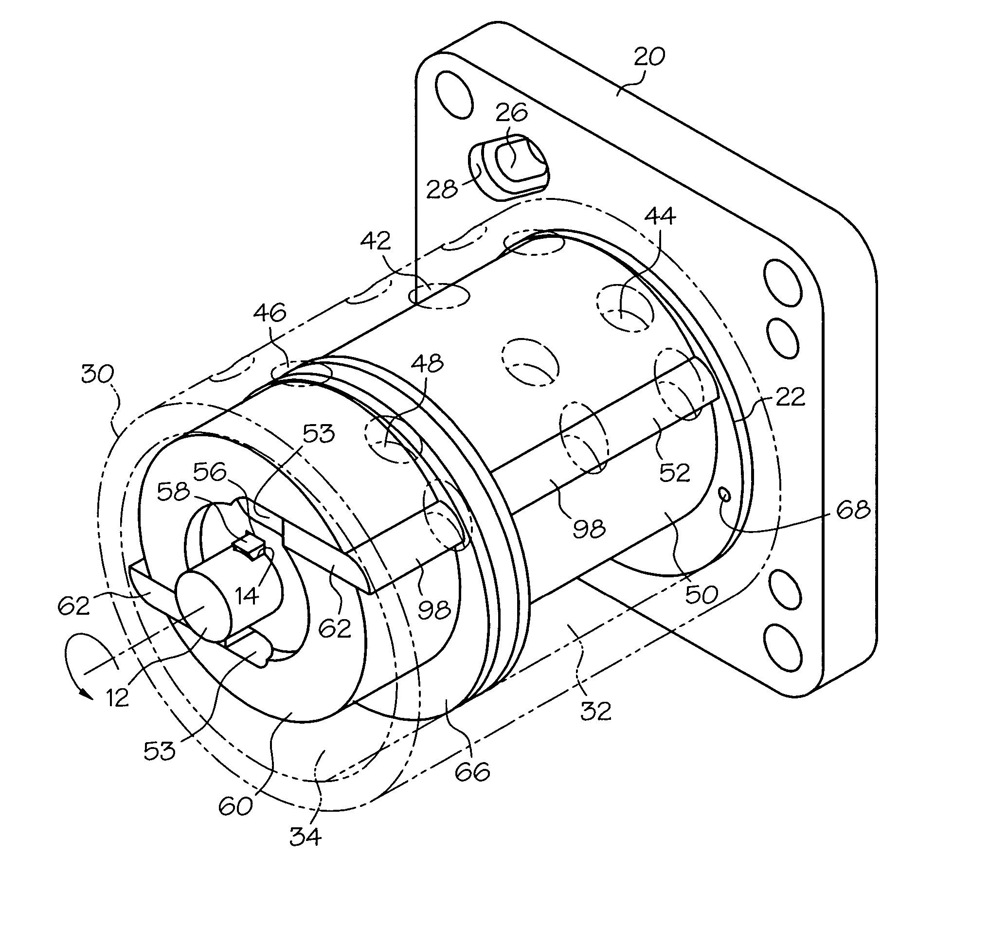
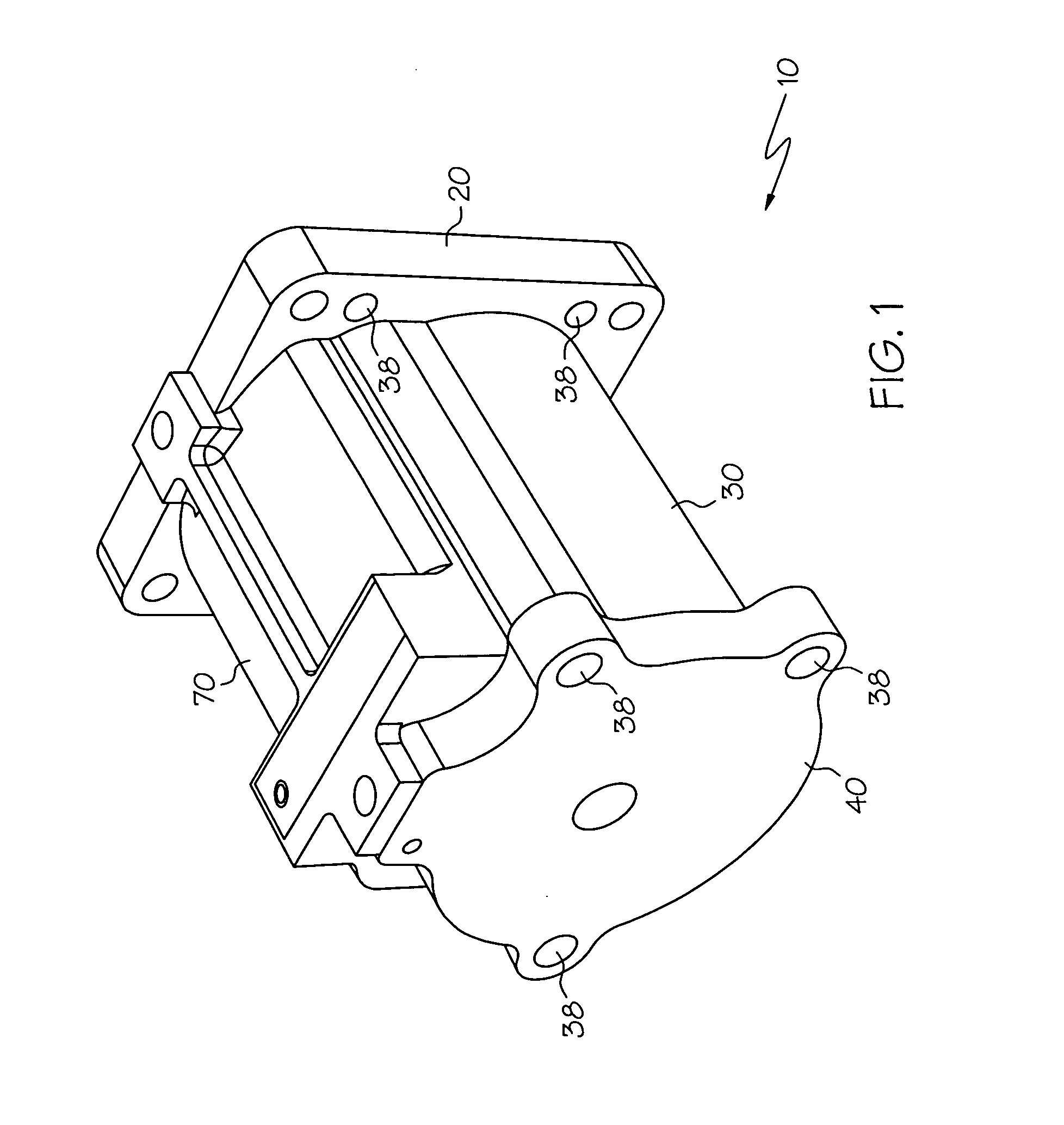
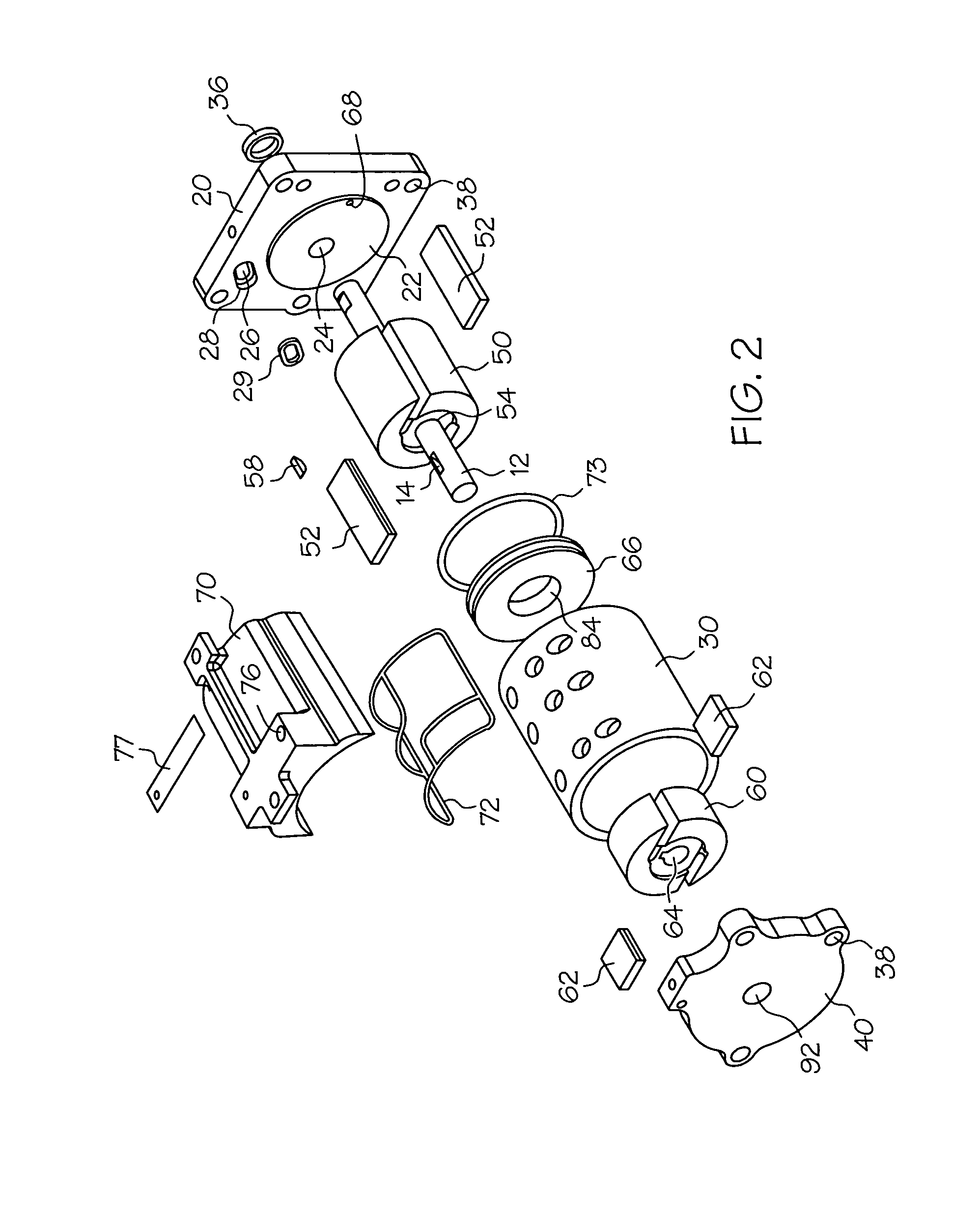
[0040]FIGS. 1 and 2 show an embodiment of an inventive vacuum pump 10, which may include a first or intake plate 20, a stator 30 having an internal cavity, a second or back plate 40, a shaft 12, a first rotor 50, a second rotor 60, a divider plate 66 and a cap 70. Each rotor 50, 60 may include at least one and desirably a plurality of vanes 52, 62. Each rotor 50, 60 may further include a longitudinal aperture 54, 64 for receiving the shaft 12. The longitudinal aperture 54, 64 of each rotor 50, 60 may be oriented along the central longitudinal axis of the ...


PUM


Abstract

A vacuum pump may include a stator located between an intake plate and a back plate. Mating portions on the intake plate and back plate may be used to properly locate the stator. The stator may comprise a tubular piece of material. The stator may include two internal pump chambers separated by a divider plate. In some embodiments, the divider plate may have a fluid passageway extending therethrough. A rotor in each chamber may include vanes and may be offset from the center of the chamber. Each rotor may be fixed to a rotatable shaft for operation of the vacuum pump.

Description

BACKGROUND OF THE INVENTION [0001] Vacuum pumps may be used for a wide variety of industrial processes, such as dehydration, decontamination, degassing, and the forming, lifting and holding of fluids. U.S. Pat. No. 4,523,897 to Lower et al. and U.S. Pat. No. 3,837,764 to Fritch et al. disclose examples of vacuum pumps. [0002] The manufacturing process of a typical vacuum pump generally requires a skilled assembly technician to establish the correct clearances between parts of the pump. This often includes expensive grinding and lapping operations. Clearances are then maintained by compressive loads applied by screws or dowel pins. [0003] It would be desirable for a pump to have a design wherein the correct clearances between internal parts may be substantially fixed as a function of the machining processes during manufacture, wherein expensive grinding and lapping operations are not required. [0004] It would be desirable for a pump to be manufactured from relatively inexpensive part...

Claims


Application Information

Patent Timeline
Patent Type & Authority Applications(United States)
IPC IPC(8): F01C19/00F04C27/00F04C15/00F04C2/00
CPCF01C21/106F04C18/3442F04C23/001F04C2230/603F04C2220/10F04C2220/50F04C29/12F04C18/3441F04C25/02
Inventor WEST, WILLIAM G.BOEHLER, DUANE H.
Owner RITCHIE ENG
Why Eureka
Try Eureka