
Method and system for establishing wireless peer-to-peer communications

a wireless peer-to-peer communication and wireless communication technology, applied in the field of self-organization wireless communication network systems for peer-to-peer communication, can solve the problems of removing valuable radio resources, unable to allocate separate channels for testing, and creating complexity in the re-allocation scheme of radio resources, so as to achieve simple and effective effects

Active Publication Date: 2006-10-12
ATREUS LABS LLC
View PDF9 Cites 56 Cited by
  • Summary
  • Abstract
  • Description
  • Claims
  • Application Information

AI Technical Summary

Benefits of technology

"The present invention provides a solution for mobile terminals to communicate with each other without needing a separate radio channel. The network system determines if the mobile terminals can communicate with each other and sends information to them to test the communication. The mobile terminals then use the same radio resources to communicate with each other, without needing additional resources. This simplifies the process and ensures the quality of the channels is the same as tested. The technical effect of this invention is to enable peer-to-peer communication between mobile terminals without needing a separate radio channel."

Problems solved by technology

However, the channel allocations for these purposes take away valuable radio resources, which are already inadequate.
Thus, if the radio resources are used up, a separate channel cannot be allocated for the test.
By allocating additional radio channels for the peer-to-peer communication, it also creates complexity in the radio resources re-allocation scheme.
Further, since the test is not directly performed on the newly allocated channels between the mobile terminals, there is no assurance that the characteristics of the new channels also meet the requirement for direct communication.

Method used


Image

  • Method and system for establishing wireless peer-to-peer communications
  • Method and system for establishing wireless peer-to-peer communications
  • Method and system for establishing wireless peer-to-peer communications

Examples


Embodiment Construction

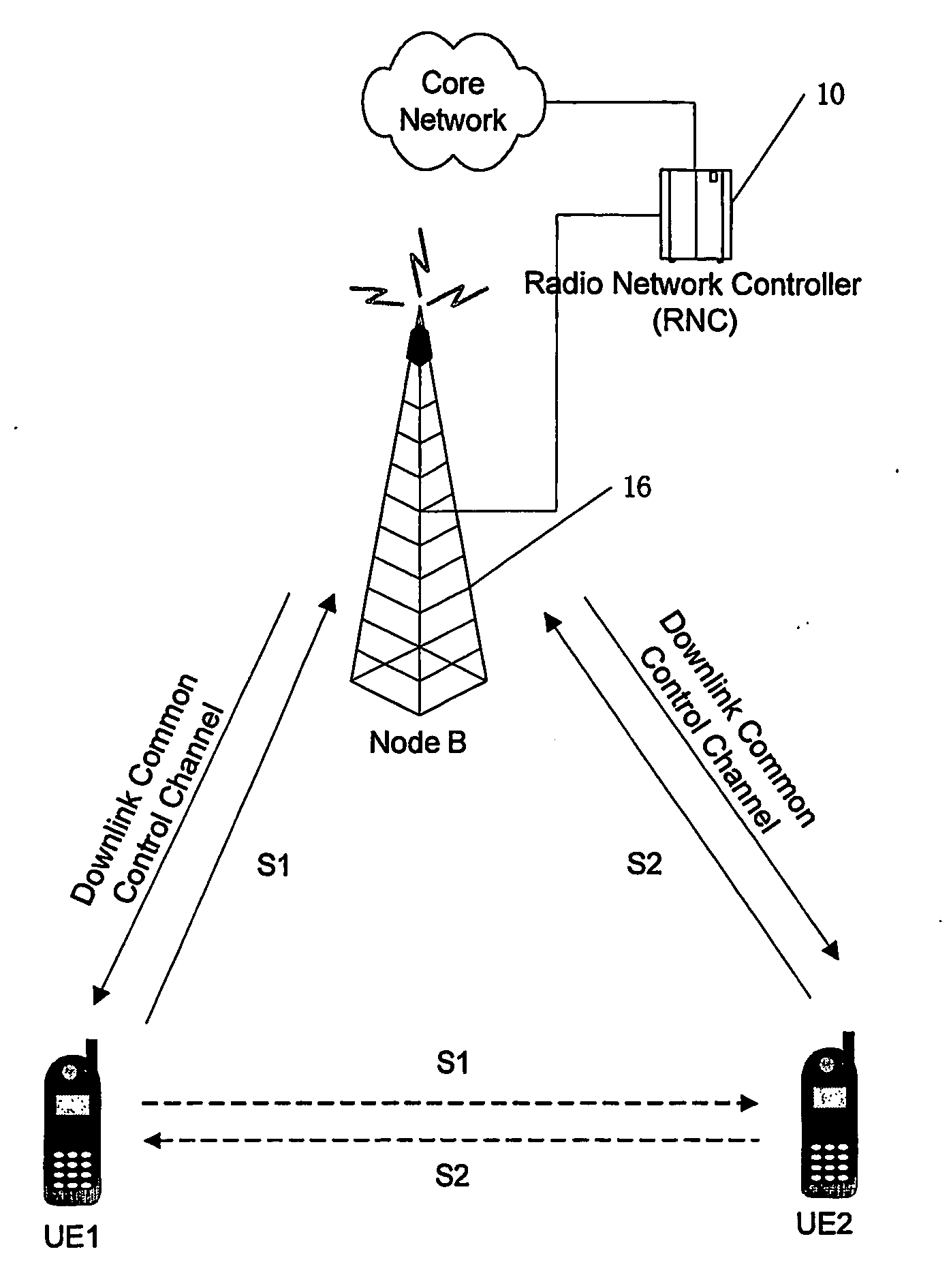
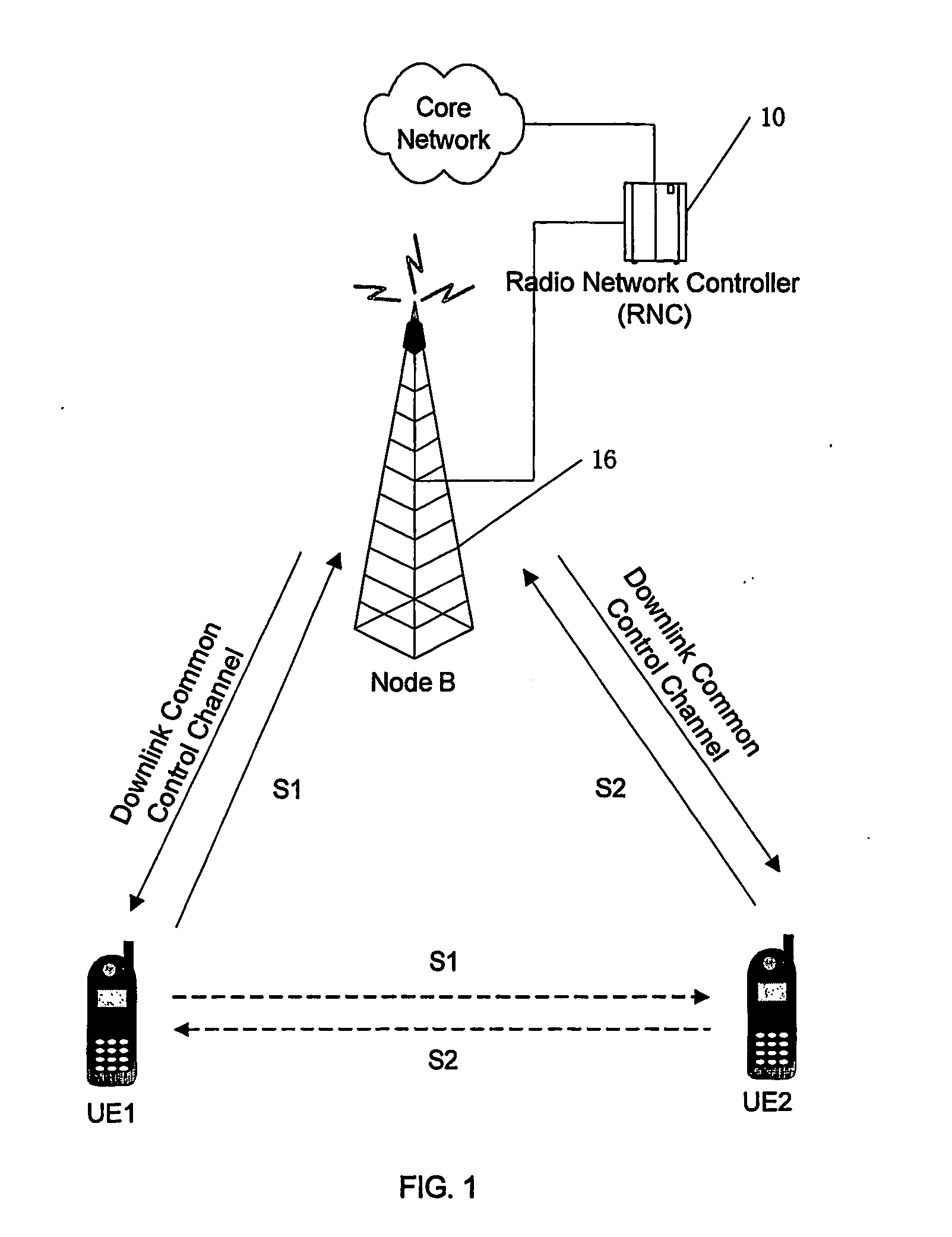
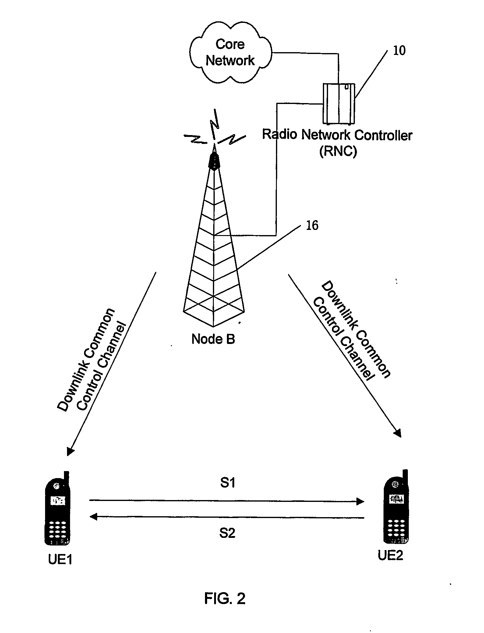
[0017]FIG. 1 illustrates an initial stage for setting up peer-to-peer communication in a wireless communication network system (e.g., Universal Terrestrial Radio Access Network (UTRAN)) environment, according to one embodiment of the invention. Before a peer-to-peer communication link is established between two mobile terminals UE1 and UE2, the UTRAN that comprises a radio network controller (RNC) 10 and a Node B (i.e., a base station) 16 will first determine whether the distance between UE1 and UE2 is within the acceptable range for peer-to-peer communication. If so, each of the mobile terminals will be requested to listen to the dedicated uplink channel, S1 or S2, between the UTRAN and the other UE (illustrated by the dash lines in FIG. 1) and test the respective channel characteristics. If the quality of the channels meets the requirements of a direct communication for a pre-determined duration, the mobile terminals will be allowed to use the radio resources originally allocated ...


PUM


Abstract

The present invention provides a wireless network system for establishing peer-to-peer communication between mobile terminals. Upon determining that peer-to-peer communication can be established between two mobile terminal, the wireless network system transmits to each of the mobile terminals information about radio resources used by the other one of the mobile terminals. Each mobile terminal then uses the radio resources information to test the characteristics of a dedicated uplink channel between the other one of the mobile terminals and the network system. Thus, no separate radio channel needs to be allocated for the channel testing. Furthermore, each mobile terminal uses the same radio resources to establish a dedicated radio channel in the peer-to-peer communication with the other one of the mobile terminals, which were previously used by itself for communication with the network system on the dedicated uplink channel. In this way, the network system does not need to allocate additional radio resources for establishing the peer-to-peer communication, thus simplifying the radio resources re-allocation scheme, while ensuring that the quality of the channels is the same as tested.

Description

BACKGROUND OF THE INVENTION [0001] The invention relates generally to wireless communications systems, and more particularly to self-organizing wireless communication network systems for peer-to-peer communication. [0002] Peer-to-peer communication between two mobile terminals provides a direct link between the two mobile terminals in public land mobile network. When the direct link is established, the dedicated links between the base station and mobile terminals can be disconnected, while the common control channel (CCCH) is maintained. This will save at least two radio channels for the system and reduce the end-to-end delay. [0003] Among existing 3G systems, the TDD CDMA system is the most suitable system for the application of peer-to-peer communication, because the same carrier frequency is used in both uplink and downlink communications, which will simplify the RF module of the mobile terminal. Additionally, the application of peer-to-peer communication technology will overcome...

Claims


Application Information

Patent Timeline
Patent Type & Authority Applications(United States)
IPC IPC(8): H04B7/00H04Q7/20H04B1/69H04B7/26H04W72/54
CPCH04W4/06H04W8/24H04W92/18H04W48/08H04W76/023H04W24/00H04W76/14
Inventor JIA, QUNLIMA, NISUN, LIZHANG, XUEJUN
Owner ATREUS LABS LLC
Learn More